
System for mounting and selectable adjustment of angle of elevation of groups of PV panels

Inactive Publication Date: 2010-10-28
JOHNSTON JR ROBERT G
View PDF8 Cites 53 Cited by
  • Summary
  • Abstract
  • Description
  • Claims
  • Application Information

AI Technical Summary

Benefits of technology

[0011]It is another object to provide a system for the suspension of PV modules above concrete and other flat roofs typical of commercial buildings, or of less than ten degrees, that is economical, and requires no special tools for installation.
[0021]It is a still further object to provide a system of the above type in which the profile of the horizontal supports thereof will facilitate collection and safe positioning of all wiring harnessing associated with the PV array system through the location of such wiring at a significantly higher level than other panel mounting strategies known in the art.

Problems solved by technology

However, the prior art, as set forth below, does not teach a mechanically simply or time and cost-effective method for selectable adjustment of the angle of elevation of such groups or assembles of PV panels after mounting to the roof.
Notwithstanding the remarkable potential for such use of solar energy, certain practical problems nonetheless subsist.
While the prior art teaches various strategies for the installation and roof support of a solar panel or systems thereof, relatively little prior art has sufficiently addressed the issue of optimizing the angle of elevation of a PV panel group and the need to be able to quickly and cost-effectively change this angle responsive to various factors as above set forth.
The prior art, as above set forth, also fails to address other important issues in regard to the mounting of PV power arrays on building roofs, these including such systems that can be readily assembled and, if needed, disassembled, upon a building roof without requirement for use with special purpose tools and in economical fashion.
The prior art also fails to address the need or desirability for PV panel array systems having sufficient elevation to permit necessary clearance between the roof and the array as not to interfere with small projections, such as vents and the like, through the roof surface, this to allow for the optimum use of the surface area of the roof so that more panels may be employed in a given area, this resulting in higher wattage yields per square foot of the system.
The prior art also does not address the need to optimize support of the considerable loads associated with a large PV panel arrays using the bar joists or other load bearing beams of the building, nor does it considered means for optimizing necessary roof penetration in order to effect essential communication with load-bearing beams in a manner that will not result in a breach of a manufacturer's warranty of the roof system.
The prior art has also not considered the substantial safety risks associated with wiring of PV systems and the high risk posed to maintenance people by such wiring which is not optimally secured or positioned, particularly in conditions of water and moisture which are common upon roofs or buildings.
The prior art also has not considered designs of PV roof arrays that would not interfere with normal roof installation and repair functions nor has it considered designs of solar panel arrays which would provide for walkways of sufficient width to permit ease of access thereto for purposes of servicing and repair of the arrays.

Method used


Image

  • System for mounting and selectable adjustment of angle of elevation of groups of PV panels
  • System for mounting and selectable adjustment of angle of elevation of groups of PV panels
  • System for mounting and selectable adjustment of angle of elevation of groups of PV panels

Examples


Embodiment Construction

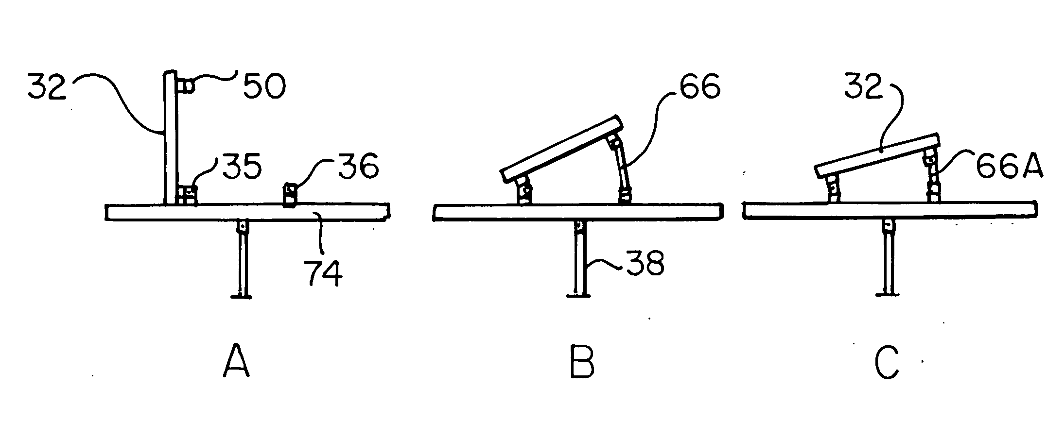
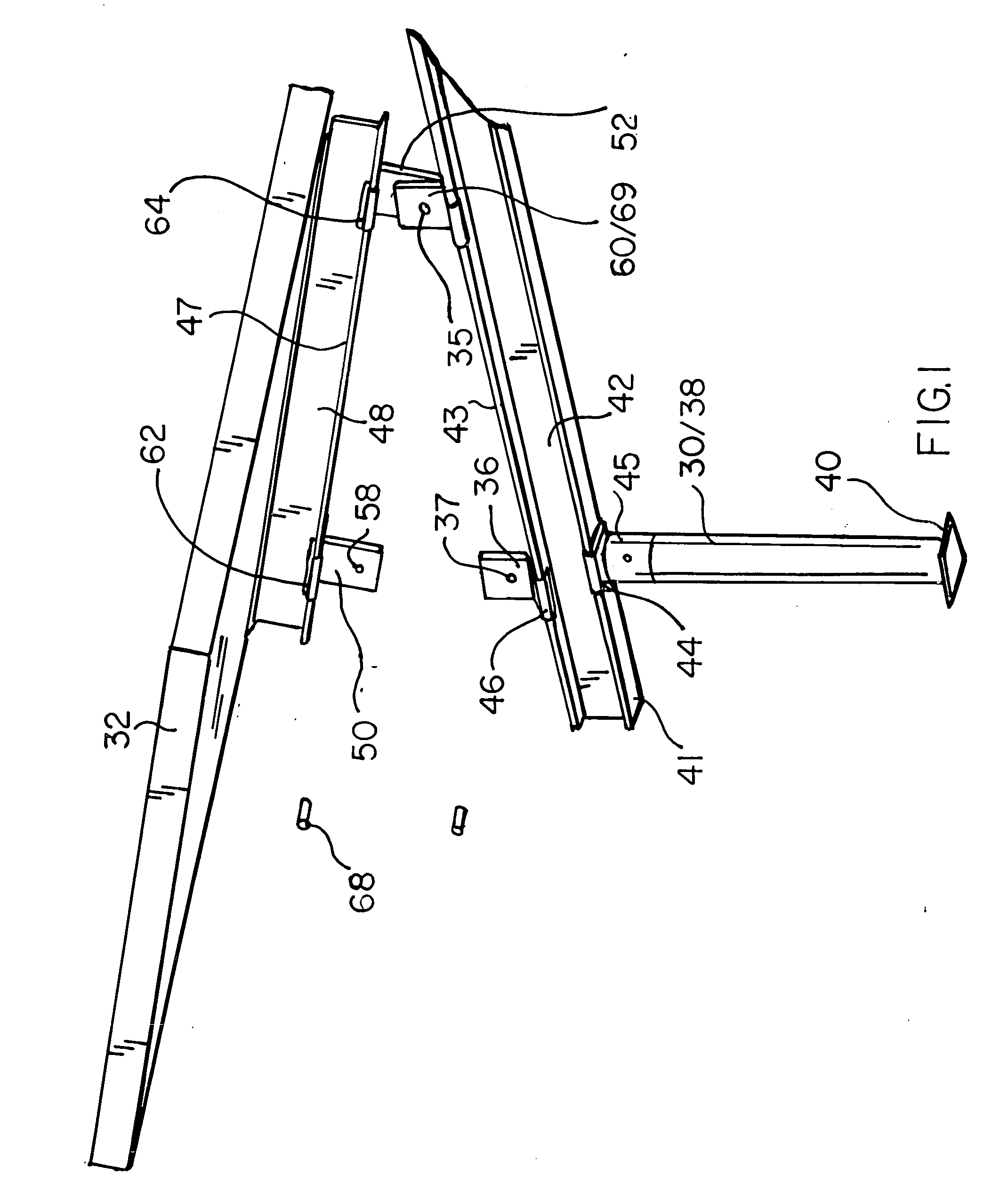
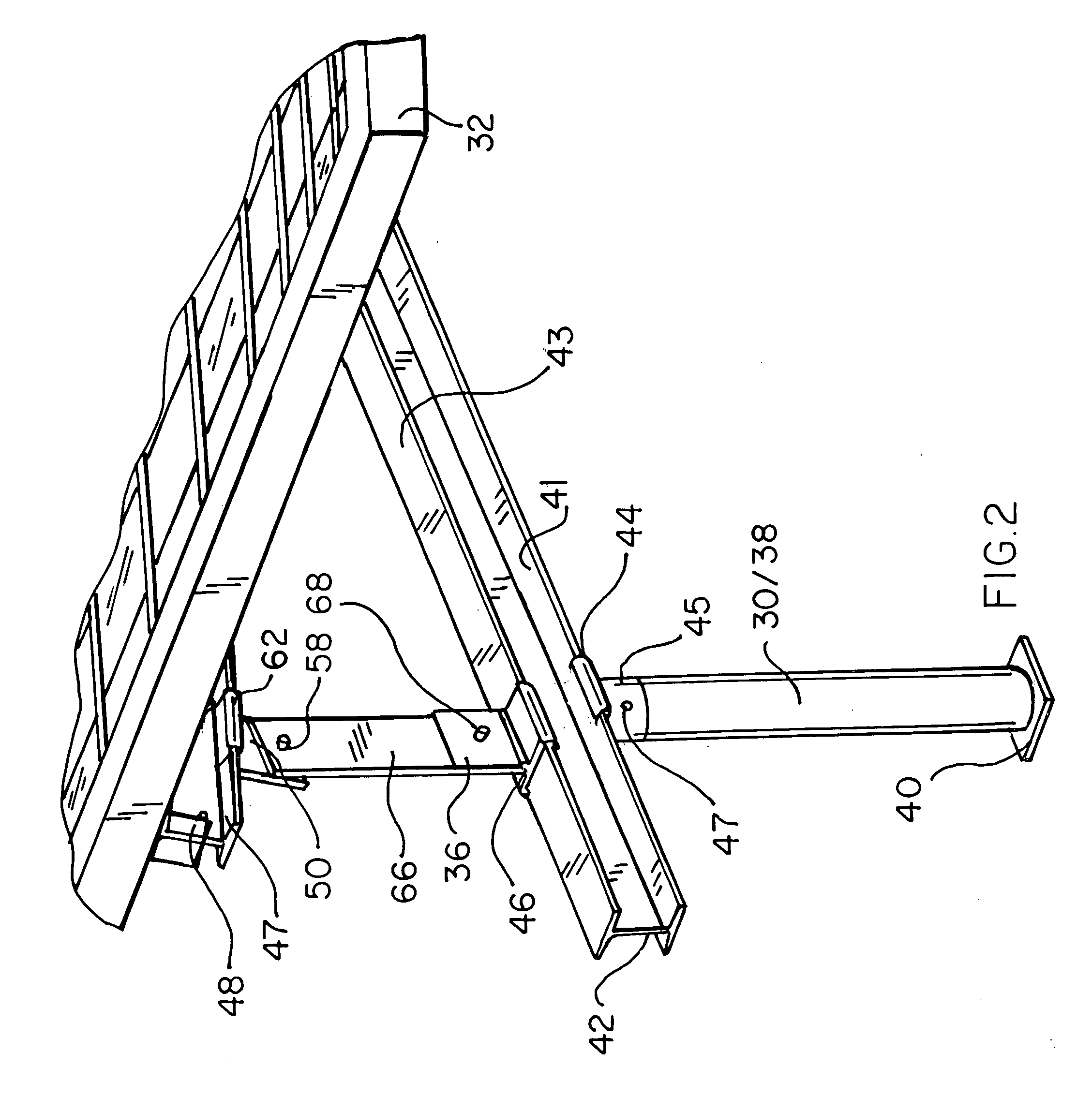
[0046]With reference to the perspective view of FIG. 1, the inventive system for the selective adjustment of the angle of elevation of groups of photo voltaic (PV) panels relative to a roof to which such panels are to be attached may be seen to include a platform 30, upon or through said roof (see FIGS. 12 and 16), of sufficient strength and stability to support one or more PV panels 32, inclusive of arrays and groups thereof. Further shown in FIG. 1 are lower couplings 46, provided upon said platform. Each of said couplings are provided with an aperture 37 within extension tabs 35 and 36 of the couplings. See also FIG. 13. As may be further noted in FIGS. 1-3, platform 30, in a preferred embodiment, includes a vertical member 38, a sleeve 45, a base 40 and an I-beam or rail 42 which is preferably secured to sleeve 45 by an integral coupling 44 which is proportioned for slidable engagement with a lower edge 41 of I-beam 42. Similarly, lower portions of said couplings 46 are proporti...


PUM


Abstract

A system for the selectable adjustment of an angle of elevation of groups of PV panels or panel arrays, relative to a roof to which the panels are attached, includes a platform, upon or thru the roof. The platform including horizontally secured rails. Also included are a parallel series of lower couplings, each member of the series provided upon the rails, and having a transverse distance between them sufficient to accommodate a PV panel array. Each of the couplings are provided with integral extensions or tabs, each having an aperture within a portion not in engagement with the platform. The system also includes linear support members secured to undersides of the panel arrays to be selectably elevated, each of the support members substantially co-planar with the rails of the parallel series of lower couplings. Struts of fixed lengths are selectably provided between alternates of the lower couplings within each of the series of couplings, in which alternate couplings, not associated with the struts, are rotationally or pivotally secured by extension tabs of each coupling and selectably secured to couplings upon the linear support members of the panel arrays. Also provided are equal length strut pairs of selectable lengths, each strut having an aperture at each end, detachably securable between corresponding lower and upper couplings of each of the series pairs of couplings between the rotational couplings. Selection of a pair of corresponding equal length struts, related to coupling pairs upon the parallel series of couplings and rails, effects an angle of elevation of a PV panel array as a function of the length of the co-equal lengths of the struts within the parallel series of couplings and rails.

Description

TECHNICAL FIELD [0001]The present invention relates generally to constructional methods for PV panel arrays, mounting hardware therefore and an improved system to effect selectable adjustment of angles of elevation of groups of PV panels relative to roofs upon which the panels are employed.BACKGROUND OF THE INVENTION[0002]As used herein, the term “PV panel” or “PV array” identify photovoltaic power generating units in the form of an integrated structure comprising a plurality of electrically interconnected photovoltaic cells and means for supporting and protecting the cells. The term “PV panel group” or the like identifies the structure comprising two or more PV modules or panels that are mechanically ganged together and are electronically interconnected to form a unitary power source.[0003]In the prior art, a variety of systems and methods have, from time-to-time, been used to effect the mounting of PV modules, arrays and associated components of electric power or PV power generati...

Claims


Application Information

Patent Timeline
IPC IPC(8): H01L31/042F16M11/04
CPCF24J2/5232F24J2/526F24J2/5264F24J2002/5213H02S20/00Y02B10/20Y02E10/47Y02E10/50Y02B10/12F24S25/12F24S25/65F24S25/70F24S2025/80H02S20/23H02S20/30Y02B10/10
Inventor JOHNSTON, JR., ROBERT G.
Owner JOHNSTON JR ROBERT G
Learn More