Current-sharing supply circuit for driving multiple sets of DC loads

a supply circuit and current-sharing technology, applied in the direction of electric variable regulation, process and machine control, instruments, etc., can solve the problems of reducing the service life of individual led strings, and reducing the service life of whole electronic devices, so as to reduce power loss, simplify circuitry configuration, and high operating efficiency

Inactive Publication Date: 2010-10-28
DELTA ELECTRONICS INC
View PDF7 Cites 15 Cited by
  • Summary
  • Abstract
  • Description
  • Claims
  • Application Information

AI Technical Summary

Benefits of technology

[0009]Another object of the present invention provides a current sharing supply circuit for driving multiple sets of DC loads, in which the current sharing supply circuit has minimized power loss, high operating efficiency and simplified circuitry configuration.
[0010]A further object of the present invention provides a current sharing supply circuit for driving multiple sets of DC loads, in which the overall volume of the current-sharing supply circuit is reduced but the circuitry density is enhanced.

Problems solved by technology

Due to different inherent characteristics of these LED strings, the currents passing therethrough are not identical and the brightness is usually not uniform.
Therefore, the use life of individual LED string is shortened or even the whole electronic device has a breakdown.
Due to different inherent characteristics of these LED strings, the currents passing these LED strings are not identical and the brightness is usually not uniform.
Therefore, the use life of individual LED string is shortened or even the whole electronic device has a breakdown
The conventional current-sharing supply circuit for driving multiple LED strings, however, still has some drawbacks.
For example, since the linear regulator and the current mirrors are employed, the conventional current-sharing supply circuit has high power loss but low operating efficiency.
In addition, since more components are used, the conventional current-sharing supply circuit is very complicated.

Method used


Image

  • Current-sharing supply circuit for driving multiple sets of DC loads
  • Current-sharing supply circuit for driving multiple sets of DC loads
  • Current-sharing supply circuit for driving multiple sets of DC loads

Examples


Embodiment Construction

[0026]The present invention will now be described more specifically with reference to the following embodiments. It is to be noted that the following descriptions of preferred embodiments of this invention are presented herein for purpose of illustration and description only. It is not intended to be exhaustive or to be limited to the precise form disclosed.

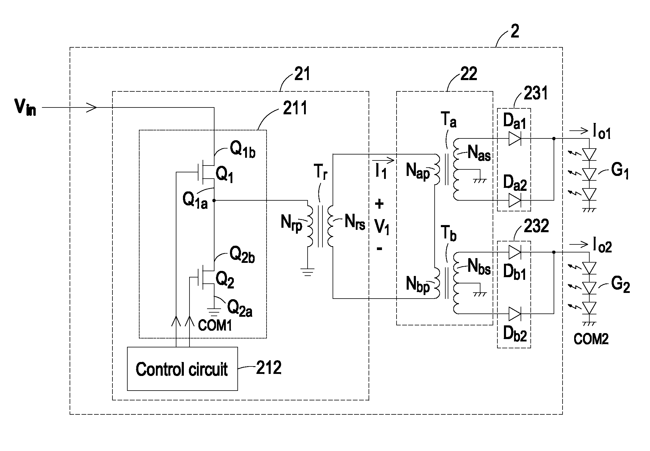
[0027]The present invention relates to a current-sharing supply circuit for driving multiple sets of DC loads, so that all sets of DC loads have the same brightness values. The multiple sets of DC loads include for example multiple LED strings. Each LED string includes a plurality of LEDs. For clarification, two LED strings, each of which has three LEDs, are shown in the drawings.

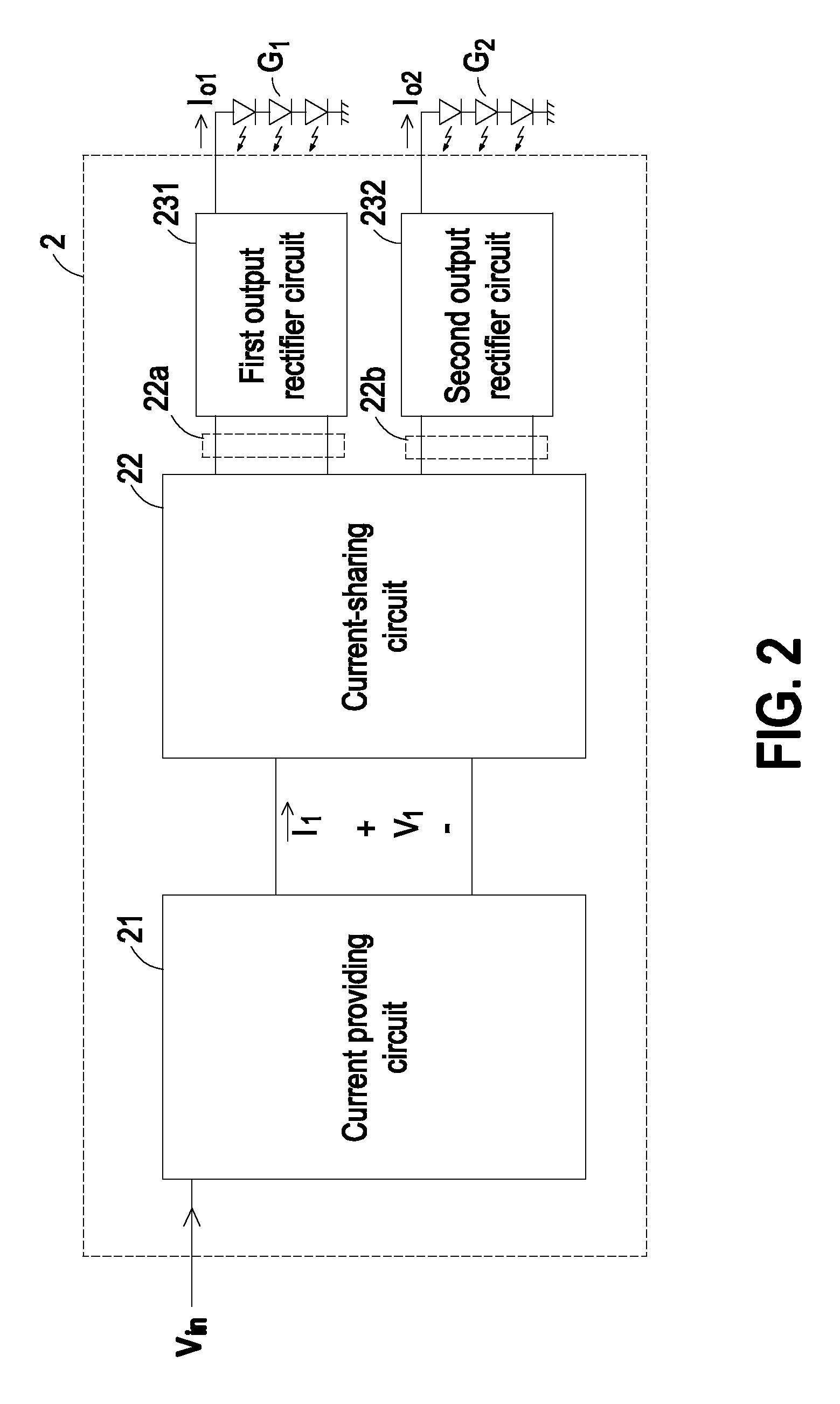
[0028]FIG. 2 is a schematic circuit block diagram of a current-sharing supply circuit for driving multiple sets of DC loads according to an embodiment of the present invention. The current-sharing supply circuit 2 is used for driving a first LED string G...


PUM


Abstract

A current-sharing supply circuit includes a current providing circuit, a current-sharing circuit, a first output rectifier circuit and a second output rectifier circuit. The current providing circuit receives an input voltage and generating a first current or a first voltage, thereby providing electrical energy to a first set of DC loads and a second set of DC loads. The first output rectifier circuit is interconnected between the first set of DC loads and a first output terminal of the current-sharing circuit, thereby generating a first output current to the first set of DC loads. The second output rectifier circuit is interconnected between the second set of DC loads and a second output terminal of the current-sharing circuit, thereby generating a second output current to the second set of DC loads. The first output current and the second output current are balanced by the current-sharing circuit.

Description

FIELD OF THE INVENTION[0001]The present invention relates to a current-sharing supply circuit, and more particularly to a current-sharing supply circuit for driving multiple sets of DC loads.BACKGROUND OF THE INVENTION[0002]In recent years, light emitting diodes (LEDs) capable of emitting light with high luminance and high illuminating efficiency have been developed. In comparison with a common incandescent light, a LED has lower power consumption, long service life, and quick response speed. With the maturity of the LED technology, LEDs will replace all conventional lighting facilities. Until now, LEDs are widely used in many aspects of daily lives, such as automobile lighting devices, handheld lighting devices, backlight sources for LCD panels, traffic lights, indicator board displays, and the like.[0003]When an electronic device (e.g. a LCD panel) having multiple LED strings is operated, the currents passing through all LED strings shall be identical for a purpose of obtaining un...

Claims


Application Information

Patent Timeline
Patent Type & Authority Applications(United States)
IPC IPC(8): H05B41/36
CPCH02M3/33569Y02B70/1433H05B33/0815Y02B70/10H05B45/382H02M3/33573H02M3/33571H02M3/01
Inventor CHANG, SHIH-HSIENKO, PO-NIEN
Owner DELTA ELECTRONICS INC
Why Eureka
Try Eureka