
Apparatus for harvesting energy from microwave

a technology of energy harvesting apparatus and microwave, which is applied in the direction of electrochemical generators, secondary cells servicing/maintenance, transportation and packaging, etc., can solve the problems of unbalanced biorhythm, inability to easily remove or weaken, and reduced sperm coun

Inactive Publication Date: 2010-10-28
ELECTRONICS & TELECOMM RES INST
View PDF16 Cites 27 Cited by
  • Summary
  • Abstract
  • Description
  • Claims
  • Application Information

AI Technical Summary

Benefits of technology

[0016]Another embodiment of the present invention is directed to providing an energy harvesting apparatus capable of reducing influence of microwave on a human body.

Problems solved by technology

A magnetic field is formed in a circular shape around a source and is not easily removed or weakened by certain objects or materials.
Hence, if a human body is exposed to the very low frequency radio wave or the low frequency radio wave for a long time, a body temperature is changed and a biorhythm is unbalanced, which is very likely to cause diseases.
For example, search results were reported that the very low frequency radio wave and the low frequency radio wave might cause the reduction in the number of sperms for men, and might cause menstrual irregularity and birth defects for women.
Furthermore, since a brain tumor might be caused in serious cases, the World Health Organization (WHO) conducted investigations, and harmfulness of the microwave has been revealed.
However, an energy reproduction technology using a solar heat has a large number of variable parameters.
Specifically, efficiency of energy is high when a solar heat is strong, but it is low when it rains or snows.
Moreover, since the sun always moves from the east to the west, optimal energy collection is difficult.
However, when no wind blows, energy cannot be produced.
Also, the wind power generator must be installed in a windy area.
Like this, location requirements for the wind power generator are hard to meet.

Method used


Image

  • Apparatus for harvesting energy from microwave
  • Apparatus for harvesting energy from microwave
  • Apparatus for harvesting energy from microwave

Examples


first embodiment

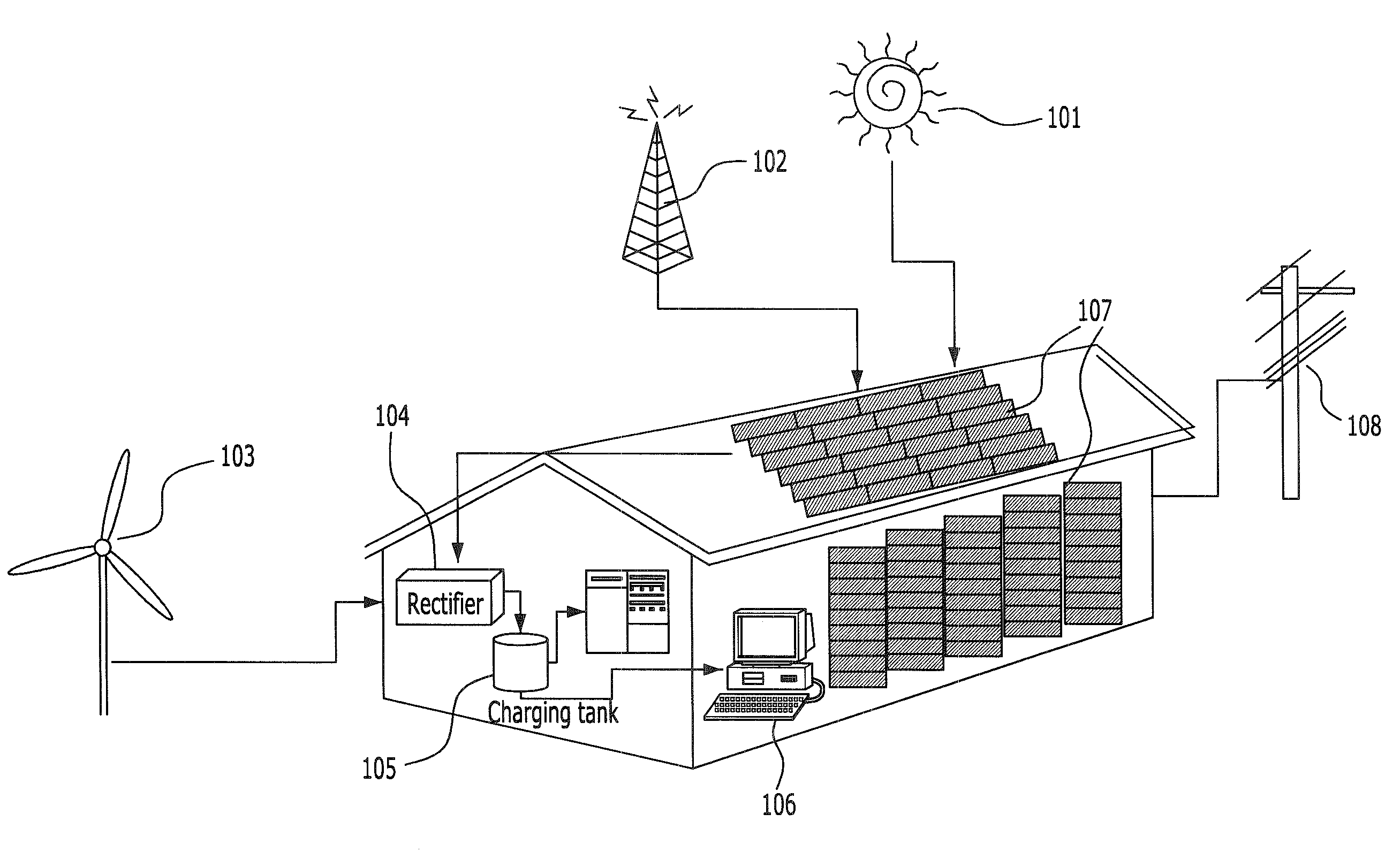
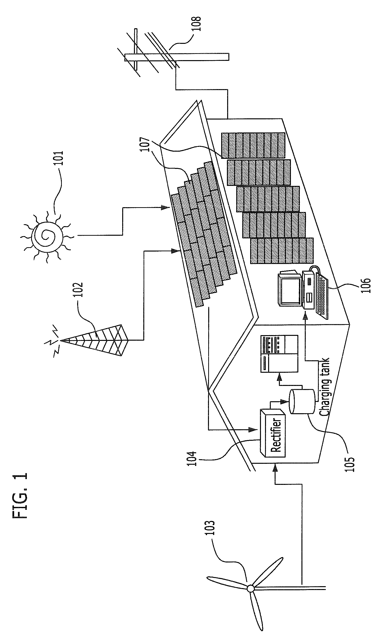
[0037]FIG. 1 is a conceptual diagram explaining a method for harvesting energy from a microwave by using an existing solar cell system in accordance with a first embodiment of the present invention.

[0038]Generally, most private homes or offices such as buildings receive AC power from an external transformer 108, and most electronic appliances use electric energy by employing an AC-DC converter. However, since a large amount of energy is lost during the conversion process, many studies have been conducted to reduce the number of AC-DC conversions by providing a DC power supply system.

[0039]Therefore, in the new energy reproduction technology, energy is stored and used by employing a DC storage battery for a DC power supply.

[0040]A representative new energy reproduction technology is to use the sun 101. Electricity is generated by using light and heat radiated from the sun 101. As the method using the sun 101, there is a solar heat technology and a photovoltaic power generation techno...

second embodiment

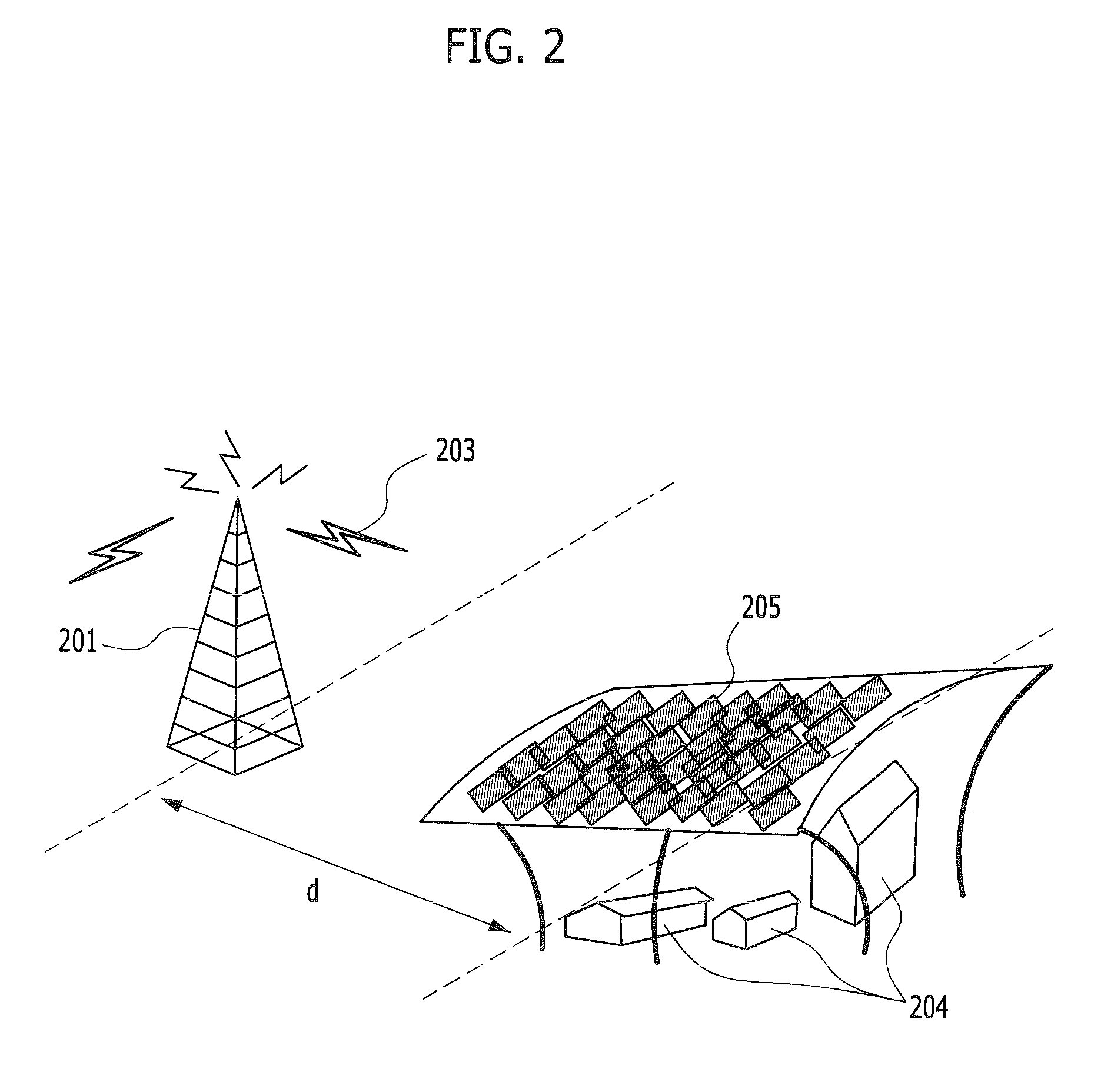
[0056]FIG. 2 is a conceptual diagram explaining a method for harvesting energy from a microwave radiated from a base station in accordance with a second embodiment of the present invention.

[0057]For convenience of life, a large number of mobile communication base stations 201 are installed around us. However, the intensity of microwave will be very strong if the mobile communication base stations 201 are installed at locations very near from the house or village 204. The above-described example is not limited to the mobile communication base station, and may include a broadcast repeater and so on. In this case, a shield 205 may be installed in order for stable communication and protection of the house or village 204 from the strong microwave 203.

[0058]Like the embodiment of FIG. 4, the shield 205 may be configured in an array form, or may be made of a transparent conductor and installed over the village, considering an amount of sunshine. The shield 205 is not limited to the embodim...

third embodiment

[0061]FIG. 3 is a conceptual diagram explaining a method for harvesting energy from a microwave generated around a high pressure power station and a transformer substation in accordance with a firth embodiment of the present invention.

[0062]The high pressure power station or transformer substation 301 or the high-voltage power transmission line 302 is considered as obnoxious facilities, and persons are reluctant to live around there. This is because persons are concerned about damage from microwave exposure because low frequency microwave is generated from those places. A low frequency generates a strong magnetic field. The control of such a magnetic field may be impossible even by the installation of a high fence.

[0063]Therefore, the method of FIG. 3 is to keep a magnetic field, which is a main cause among microwaves generated at the high pressure power station, reproduce electric energy, ensure the safety around the transformer substation, and harvest energy by using the magnetic ...


PUM

PropertyMeasurementUnit
energyaaaaaaaaaa
lengthaaaaaaaaaa
electric energyaaaaaaaaaa

Abstract

Provided is an apparatus for harvesting energy from a microwave. An apparatus for harvesting energy from a microwave in an electricity storage system of a building, includes: a plurality of rectennas arranged with a predetermined length according to characteristic of microwave to be absorbed, and configured to collect microwave in the atmosphere and convert the collected microwave into electric energy; a current converter configured to convert the electric energy outputted from the rectennas into a storable current; and a charging tank configured to store the current outputted from the current converter, wherein the arranged rectennas are attached to an outer wall of the building, and the rectennas attached to the top of the building are printed in a transparent conductor on the surface of a solar cell.

Description

CROSS-REFERENCE(S) TO RELATED APPLICATIONS[0001]The present invention claims priority of Korean Patent Application No(s). 10-2009-0037190, filed on Apr. 28, 2009, which is incorporated herein by reference in its entirety.BACKGROUND OF THE INVENTION[0002]1. Field of the Invention[0003]The present invention relates to an energy harvesting apparatus; and, more particularly, to an apparatus for harvesting energy from a microwave.[0004]2. Description of Related Art[0005]Generally, a microwave is energy generated from a flow of electricity and magnetism and is also called a radio wave. That is, an electric field and a magnetic field are simultaneously generated around an area where vibration occurs while electricity is flowing, and a wave generated while the electric field and the magnetic field vary periodically is called a microwave. Such a microwave exists everywhere.[0006]A microwave may be classified into electric fields generated by a voltage, and magnetic fields generated by a curr...

Claims


Application Information

Patent Timeline
Patent Type & Authority Applications(United States)
IPC IPC(8): H01M10/46H02J7/00
CPCH02J5/005H01M10/46H02J7/35Y02E10/76Y02E60/10H02J50/402H02J50/001H02J50/70H02J50/20H02J50/40H02J50/005
Inventor CHO, IN-KUIMOON, JUNG-ICKYUN, JE-HOONKWON, JONG-HWA
Owner ELECTRONICS & TELECOMM RES INST
Learn More