Faraday effect current sensor

a current sensor and field technology, applied in the field of sensor assembly, can solve the problems of difficult, if not impossible, correct determination of lightning curren

Active Publication Date: 2010-10-28
LANDIS & GYR OY
View PDF73 Cites 8 Cited by
  • Summary
  • Abstract
  • Description
  • Claims
  • Application Information

AI Technical Summary

Benefits of technology

[0053]The advantage of the method according to the fourth aspect of the present invention is that it essentially eliminates to influence of the following typical noise sources:

Problems solved by technology

It is a disadvantage of the Faraday sensor suggested in JP 07043392 that external magnetic fields, i.e. magnetic fields other that the magnetic field generated by the lightning current, may easily influence measurements performed by the sensor suggested in JP 07043392.
Since the Faraday sensor suggested in JP 07043392 is sensitive to non-lightning related magnetic fields correct determination of the lightning current may be difficult, if not impossible.

Method used


Image

  • Faraday effect current sensor
  • Faraday effect current sensor
  • Faraday effect current sensor

Examples


Embodiment Construction

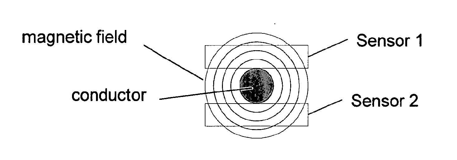
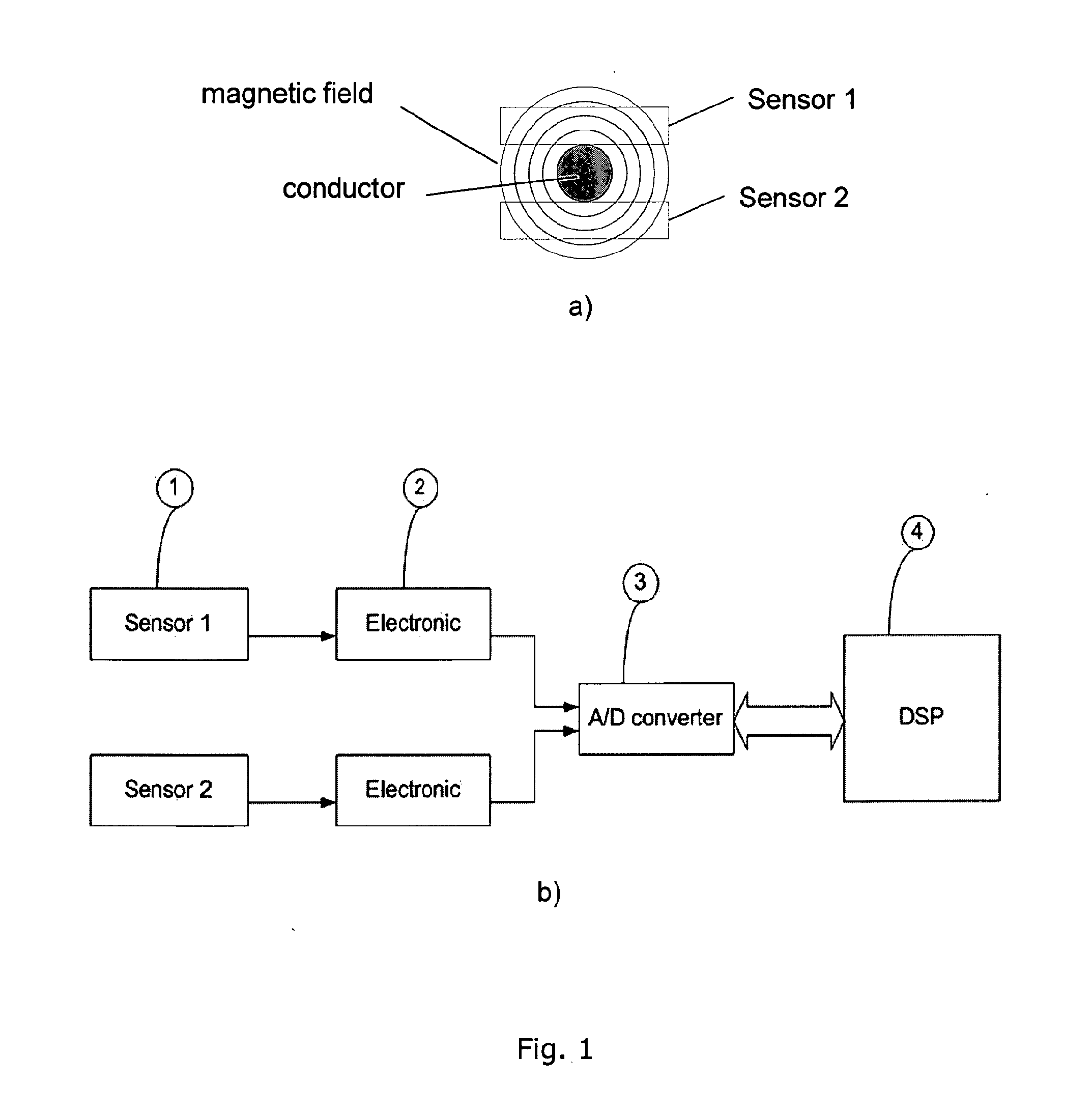
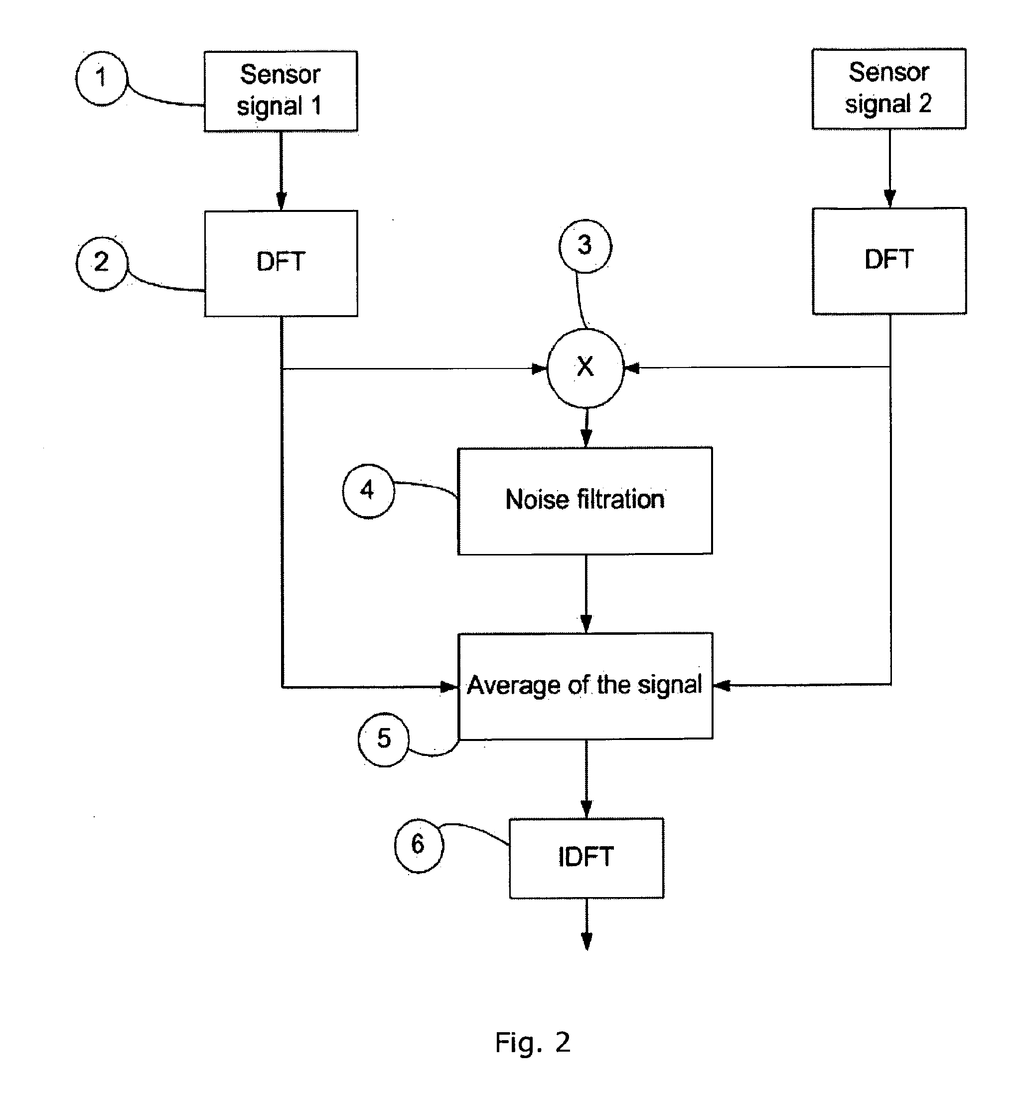
[0117]In its most general concept, the present invention relates to a sensor arrangement comprising a pair of essentially oppositely arranged Faraday sensors. By oppositely is meant that two beams of electromagnetic radiation are guided in essentially opposite propagation directions in a magnetic field generated by an electrically conducting element. The two beams of electromagnetic radiation are guided by a pair of transparent elements, such as glass rods, arranged on opposite sides of the electrically conducting element. As previously stated, the electrically conducting element may be implemented as an electrically conducting wire, a substantially rigid rod, a construction part of a rotor blade etc. The present invention further relates to noise filtration and DC compensation techniques. The individual aspects of the present invention will be described independently in the following sections.

Noise Filtration

[0118]Wherever sensors are used there is a need to filtrate noise from sen...


PUM


Abstract

The present invention relates to a Faraday sensor assembly comprising a first light guiding element adapted to guide electromagnetic radiation along a first propagation direction, and a second light guiding element adapted to guide electromagnetic radiation along a second propagation direction, the second propagation direction being essentially oppositely arranged relative to the first propagation direction. The Faraday sensor assembly further comprises a measurement region arranged between the first and second light guiding elements, the measurement region being adapted to receive an electrically conducting element having, in the measurement region, its primary extension direction in a direction being essentially perpendicular to the first and second propagation directions. The present invention further relates to methods and systems for stabilizing output signal from the sensors, and to methods and systems for processing signals from the sensor assembly.

Description

FIELD OF THE INVENTION[0001]The present invention relates to a sensor assembly for measuring or time resolving fast electromagnetic fields originating from for example strokes of lightning. The measured or time resolved electromagnetic fields are generated by currents flowing in an electrical conductor. The assembly according to the present invention comprises a pair of identical but oppositely arranged Faraday sensors. In addition, the present invention relates to methods and systems for stabilizing output signal from the sensors, and to methods and systems for processing signals from the sensor assembly.BACKGROUND OF THE INVENTION[0002]Various arrangements for measuring lightning currents have been suggested in the patent literature.[0003]JP 07043392 discloses a Faraday sensor facilitating measurements of lightning currents by measuring the angle of rotation of linearly polarised light propagating in a magnetic field which is generated by the lightning current.[0004]The Faraday se...

Claims


Application Information

Patent Timeline
Patent Type & Authority Applications(United States)
IPC IPC(8): G01R19/00G01R29/00
CPCG01R33/0322G01R15/246
Inventor BJORN, LARS NORGAARD
Owner LANDIS & GYR OY
Why Eureka
Try Eureka