
Open Fuse Detection by Neutral Point Shift

a neutral point shift and open fuses technology, applied in the direction of fuses testing, testing circuits, instruments, etc., can solve the problems of no longer receiving current, affecting the performance of the system, and literally melting of the current-carrying portion of the fuse, so as to reduce the risk of damage

Active Publication Date: 2010-10-28
TOSHIBA INT
View PDF8 Cites 16 Cited by
  • Summary
  • Abstract
  • Description
  • Claims
  • Application Information

AI Technical Summary

Benefits of technology

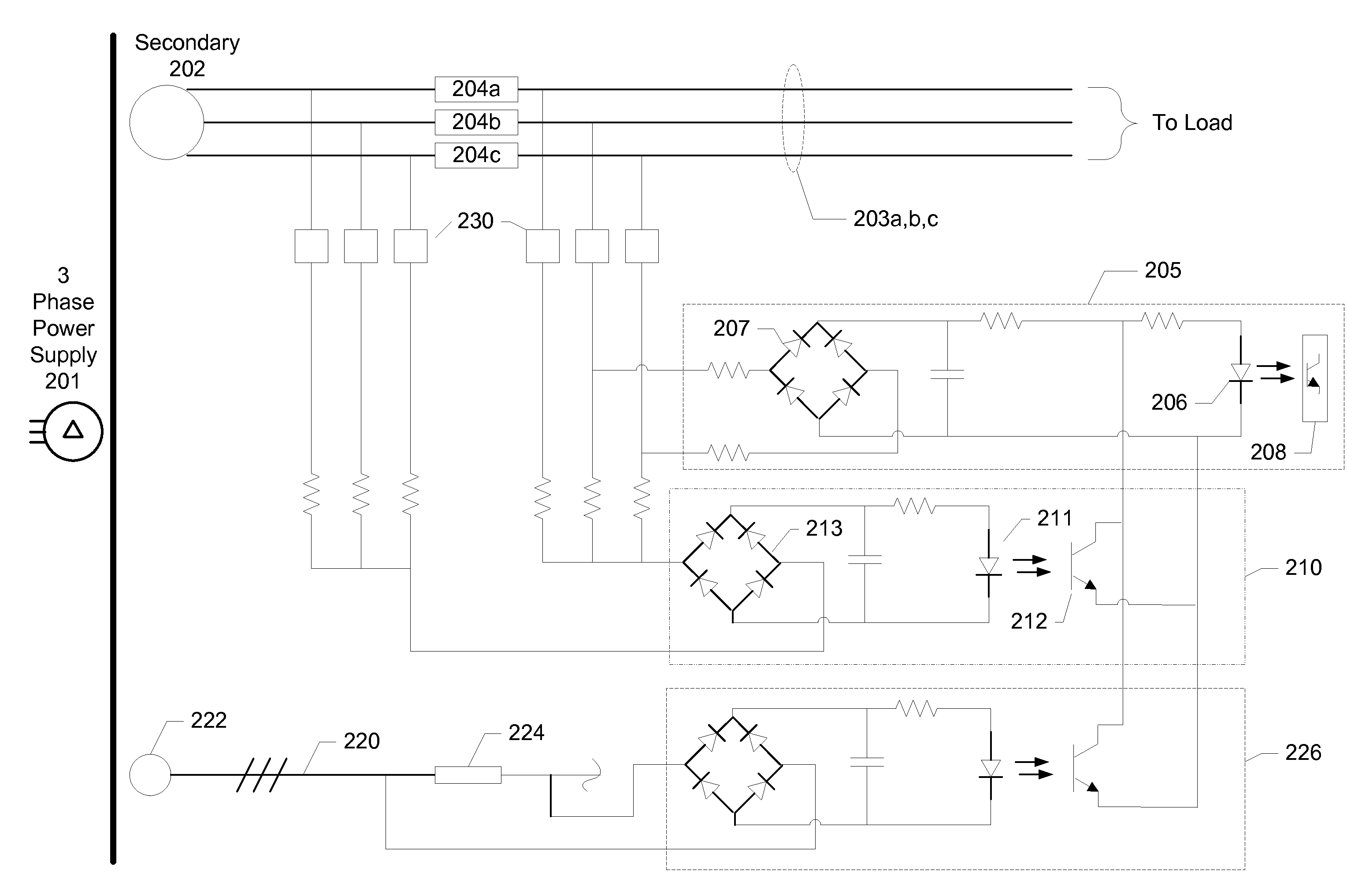
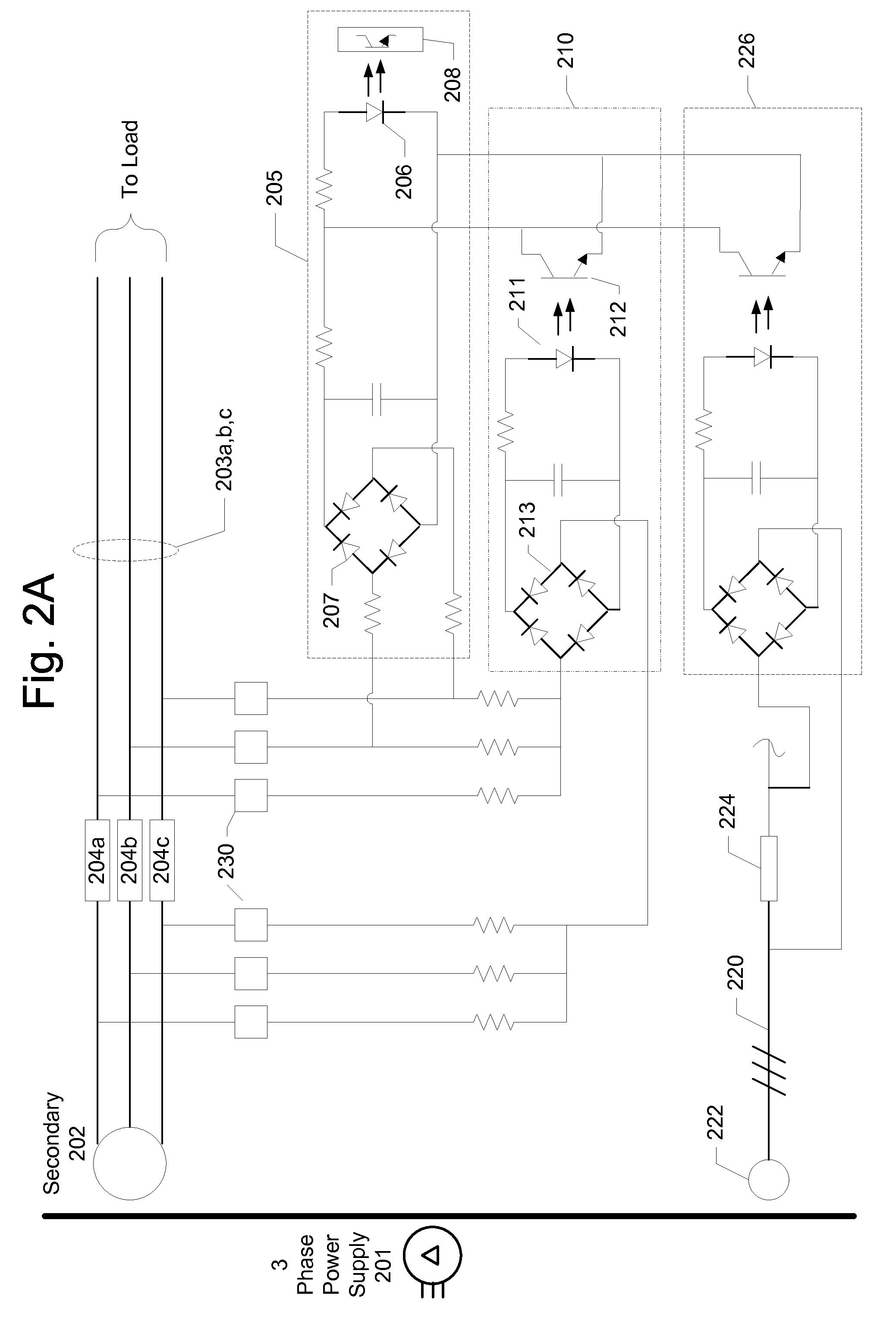
[0011]Using the above, the system may monitor for blown fuses by detecting three-phase neutral point shift between the two positions, and infer a blown fuse from such a shift. Photocouplers may be used to provide electrical isolation between the comparator circuit and the monitoring circuit, and when a blown fuse is detected, the system may act to sound an alarm, display an alert, and / or shut down system components to reduce risk of damage.

Problems solved by technology

Fuses are presently used to protect electrical circuitry from excessive current flow, and a current-carrying portion of the fuse will literally melt, or “blow,” when the current passing through the fuse rises too high.
When a fuse blows, it opens the electrical circuit path it was in, and components relying on the current flowing through that path no longer receive the current.
In some situations, the opening of that electrical circuit path might not be immediately apparent to an operator of the system, and damage can occur to components in the system.
This increased current draw risks damaging components in the system.
However, the traditional method of detecting a blown fuse—a visual inspection of the fuse itself—may not be quick enough to avoid that damage.
Such switched fuses are helpful, but they are not always available.
It may be difficult, if not impossible, to find a switched fuse with enough voltage isolation to allow it to be used for such higher voltage applications.
However these systems may require the use of a large number of isolation devices (one per fuse) for three phase systems.
When there are multiple three phase circuits involved, it can become expensive to monitor each fuse individually.

Method used


Image

  • Open Fuse Detection by Neutral Point Shift
  • Open Fuse Detection by Neutral Point Shift
  • Open Fuse Detection by Neutral Point Shift

Examples


Embodiment Construction

[0019]In the following description, reference is made to the accompanying drawings, which form a part hereof, and in which is shown by way of illustration various features that may be used. It is to be understood that other embodiments may be utilized and structural and functional modifications may be made without departing from the scope and spirit of the present application.

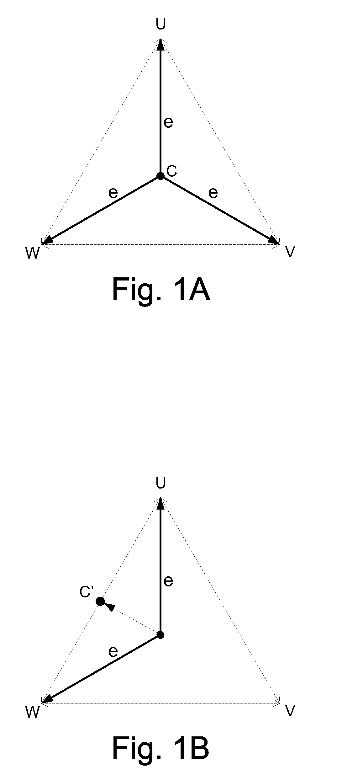
[0020]As will be described further below, features herein may detect a blown fuse in a three-phase system by monitoring the neutral point of the three phases before and after the fuses. FIG. 1A illustrates a phase diagram showing the angular relationship and magnitude (e) of the three phases (U, V, W), and how the central neutral point (C) is positioned during normal operation. In FIG. 1B, the V-phase line has suffered a break (e.g., blown fuse), and the resulting two-phase system no longer has the same central neutral point (C). Instead, the neutral point has shifted to a different phase / magnitude position. Ci...


PUM


Abstract

Systems and methods are shown for detecting a blown fuse in a three-phase line by comparing neutral points in the line before and after the fuses. Diode rectifier circuits may be used to compare the neutral points and generate a DC output voltage when neutral points are off from one another, and photocoupler circuits may provide electrical isolation when signaling a neutral point shift. The neutral points compared need not be on immediate sides of the fuses, so intermediate components may exist, and in some embodiments one of the compared points may be within a load connected to the three-phase line.

Description

FIELD OF THE SPECIFICATION[0001]The present application relates generally to three-phase power systems, and more particularly to detecting open fuses in a three-phase power system.BACKGROUND[0002]Fuses are presently used to protect electrical circuitry from excessive current flow, and a current-carrying portion of the fuse will literally melt, or “blow,” when the current passing through the fuse rises too high. When a fuse blows, it opens the electrical circuit path it was in, and components relying on the current flowing through that path no longer receive the current. In some situations, the opening of that electrical circuit path might not be immediately apparent to an operator of the system, and damage can occur to components in the system. For example, a three-phase power supply system may supply power to a load, and if a fuse blows in one of the phases, some types of loads will, by the nature of their operation (e.g., and not necessarily by design), draw increased current from...

Claims


Application Information

Patent Timeline
IPC IPC(8): G01R31/02H02H3/00G08B21/00G01R31/74
CPCG01R31/026H02H3/083H02H3/046G01R31/07G01R31/54G01R31/74
Inventor OKA, TOSHIAKIDASKALOS, MIKE C
Owner TOSHIBA INT
Learn More