Anti-collision method for drilling wells

a well-bore anti-collision and drilling technology, applied in the direction of instruments, measurement devices, constructions, etc., can solve the problems of limited well bore direction accuracy, inclination, depth measurement, and increase in well position uncertainty

Active Publication Date: 2010-10-28
SCHLUMBERGER TECH CORP
View PDF49 Cites 51 Cited by
  • Summary
  • Abstract
  • Description
  • Claims
  • Application Information

AI Technical Summary

Benefits of technology

[0008]In accordance with one embodiment of the invention, a method of drilling a new well in a field having an existing cased well includes drilling the new well using a bottom hole assembly (BHA) having a drill collar having by an insulated gap, generating a current on the BHA while drilling the new well, such that some of the current passes through a surrounding formation and travels along a casing of the existing cased well, measuring from the BHA a magnetic field caused by

Problems solved by technology

With conventional drilling practices, the uncertainties in a well's position increase as the depth of the well increases.
The uncertainties in the well position arise from the limited accuracy of the well bore direction, inclination, and depth measurements which may be obtained from MWD and/or wireline surveys, as documented extensively.
Thus, under-sampling may significantly increase the actual errors in the well position.
An additional source of survey error arises because the directional measurement is based on the magnetic field, which requires correction for variations in the Earth's magnetic field, and which can also be strongly perturbed by nearby casing.
If the casings are very close to the well path, then the MWD directional measurement m

Method used


Image

  • Anti-collision method for drilling wells
  • Anti-collision method for drilling wells
  • Anti-collision method for drilling wells

Examples


Embodiment Construction

[0046]One or more specific embodiments of the present invention are described below. In an effort to provide a concise description of these embodiments, not all features of an actual implementation are described in the specification. It should be appreciated that in the development of any such actual implementation, as in any engineering or design project, numerous implementation-specific decisions must be made to achieve the developers' specific goals, such as compliance with system-related and business-related constraints, which may vary from one implementation to another. Moreover, it should be appreciated that such a development effort might be complex and time consuming, but would nevertheless be a routine undertaking of design, fabrication, and manufacture for those of ordinary skill having the benefit of this disclosure.

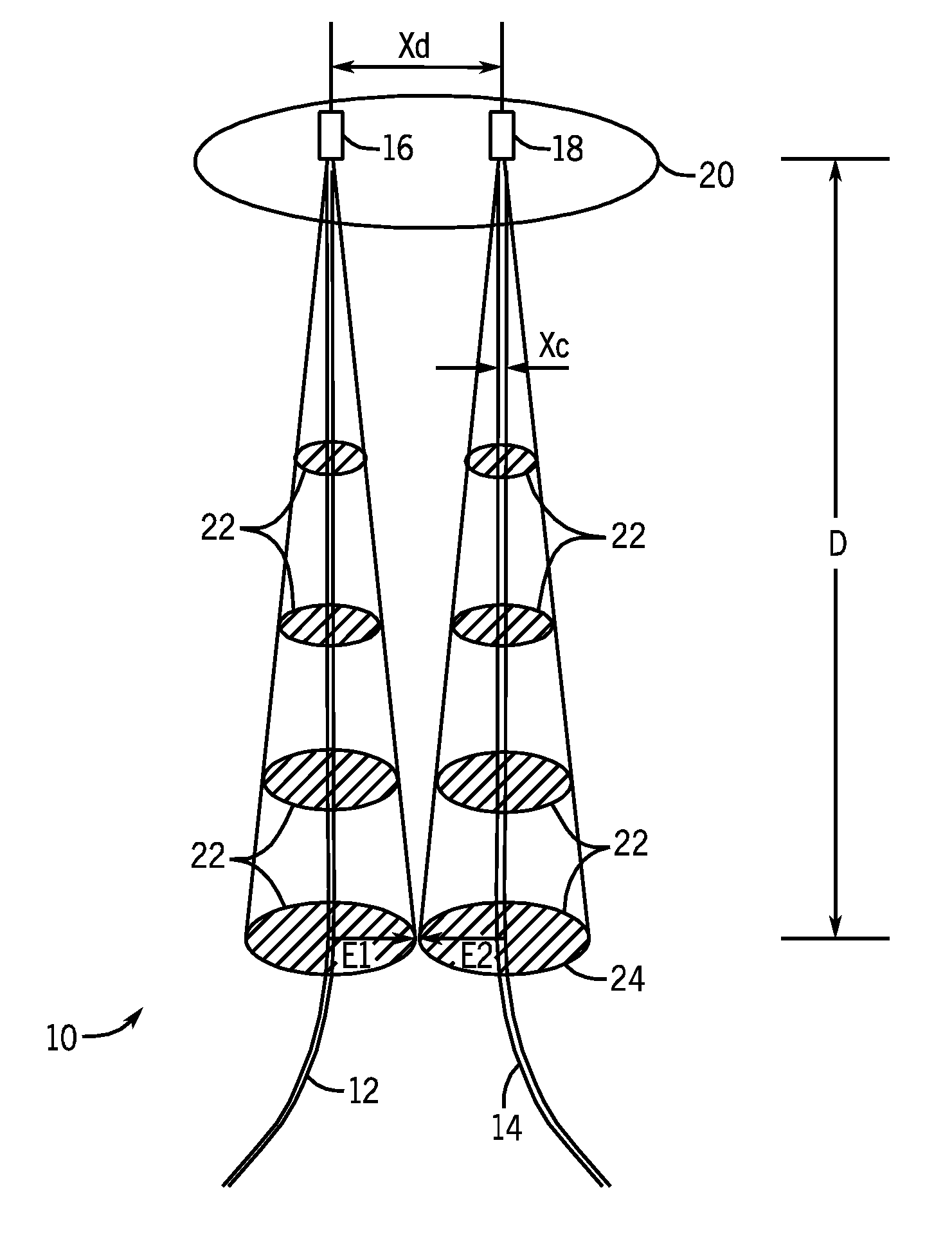
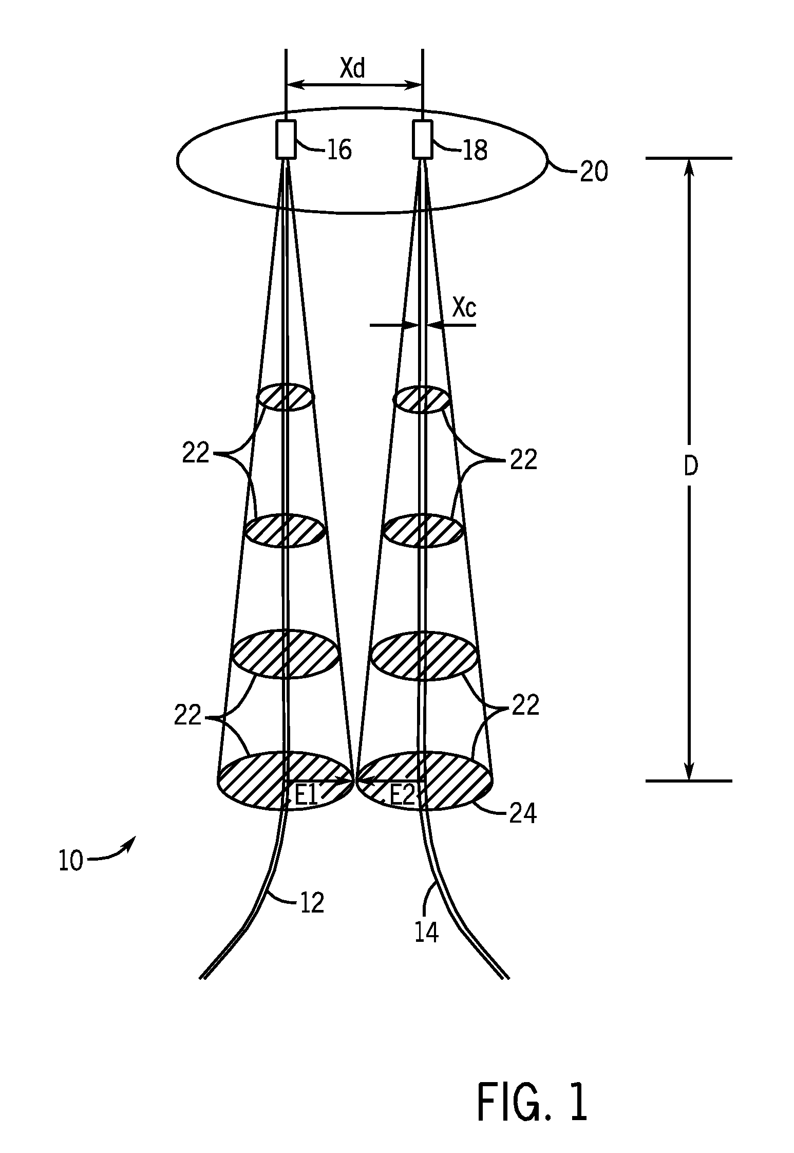
[0047]FIG. 1 is a schematic 10 illustrating the spacing of two proximate wells at an offshore platform. A first well 12 and a second well 14 have wellheads 16...


PUM


Abstract

Methods for drilling a new well in a field having a plurality of existing cased wells using magnetic ranging while drilling are provided. In accordance with one embodiment, a method of drilling a new well in a field having an existing cased well includes drilling the new well using a bottom hole assembly (BHA) having a drill collar having by an insulated gap, generating a current on the BHA while drilling the new well, such that some of the current passes through a surrounding formation and travels along a casing of the existing cased well, measuring from the BHA a magnetic field caused by the current traveling along the casing of the existing cased well, and adjusting a trajectory of the BHA to avoid a collision between the new well and the existing cased well based on measurements of the magnetic field.

Description

BACKGROUND OF THE INVENTION[0001]The present invention relates generally to well drilling operations and, more particularly, to well drilling operations using magnetic ranging while drilling to avoid collisions with existing cased wells.[0002]With conventional drilling practices, the uncertainties in a well's position increase as the depth of the well increases. These uncertainties are usually represented as ellipsoids that are centered on the location of the well as determined by Measurement While Drilling (MWD) or wireline survey data. An ellipsoid corresponds to a certain probability density corresponding to whether the well bore is actually located within the ellipsoid. The uncertainties in the well position arise from the limited accuracy of the well bore direction, inclination, and depth measurements which may be obtained from MWD and / or wireline surveys, as documented extensively. For example, MWD inclination measurements are typically accurate to no better than 0.1°, while M...

Claims


Application Information

Patent Timeline
IPC IPC(8): G01V3/00
CPCE21B47/02216E21B47/0228
Inventor CLARK, BRIANPHILLIPS, WAYNE J.POEDJONO, BENNY
Owner SCHLUMBERGER TECH CORP
Why Eureka
Try Eureka