Water jacket for cooling an electronic device on a board

a technology for electronic devices and water jackets, which is applied in the direction of power cables, semiconductor/solid-state device details, cables, etc., can solve the problems of limiting the improvement of cooling efficiency and becoming high in temperature, and achieve the effect of raising the flow rate and raising the cooling efficiency of electronic devices by the coolan

Active Publication Date: 2010-10-28
ADVANTEST CORP
View PDF8 Cites 5 Cited by
  • Summary
  • Abstract
  • Description
  • Claims
  • Application Information

AI Technical Summary

Benefits of technology

[0023]In the present invention, by running a coolant through a throttle part which has a flow passage sectional area is smaller than other parts in a channel, the coolant rises in flow rate, so the cooling efficiency of an electronic device by the coolant can be raised.

Problems solved by technology

Among the test devices mounted on the pin electronics cards, there are ones which become high in temperature when testing the DUTs due to their self generated heat.
For this reason, when the flow volume of the coolant supplied to the water jacket is limited to a certain volume, there has been a limit to the improvement of the cooling efficiency.

Method used


Image

  • Water jacket for cooling an electronic device on a board
  • Water jacket for cooling an electronic device on a board
  • Water jacket for cooling an electronic device on a board

Examples


first embodiment

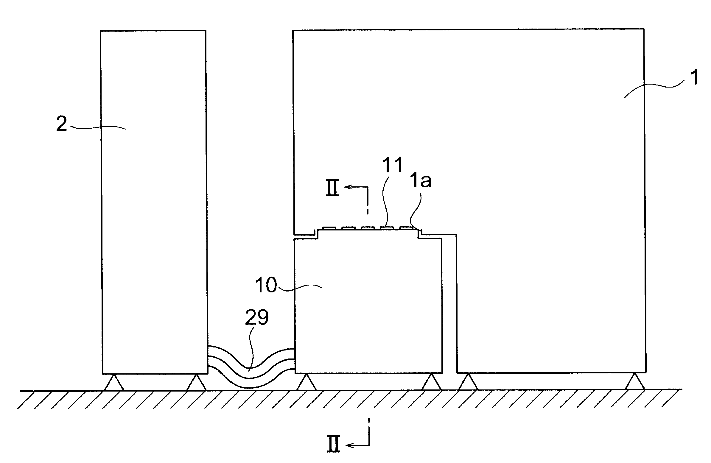
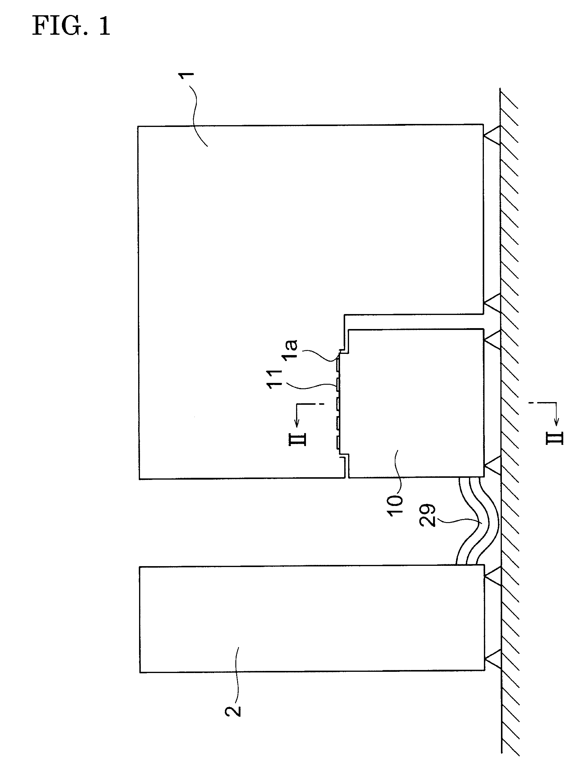
[0066]The electronic device test apparatus in the present invention, as shown in FIG. 1, for example, comprises: a handler 1 for handling a DUT; a test head 10 to be electrically connected to a DUT; and a tester body 2 for sending a test signal through the test head 10 to a DUT to run a test on the DUT. This electronic device test apparatus tests (inspects) whether the DUT is suitably operating in the state applying high temperature or low temperature thermal stress to the DUT and classifies the DUT according to the test results.

[0067]As shown in FIG. 1, a socket 11 which electrically contacting a DUT when testing the DUT is provided at the top of the test head 10. This socket 11, as shown in the same figure, approaches the inside of the handler 1 through an opening 1a formed in the handler 1. The DUT conveyed in the handler 1 is pushed against this socket 11. Note that, as the handler 1, a heat plate type or chamber type may be used.

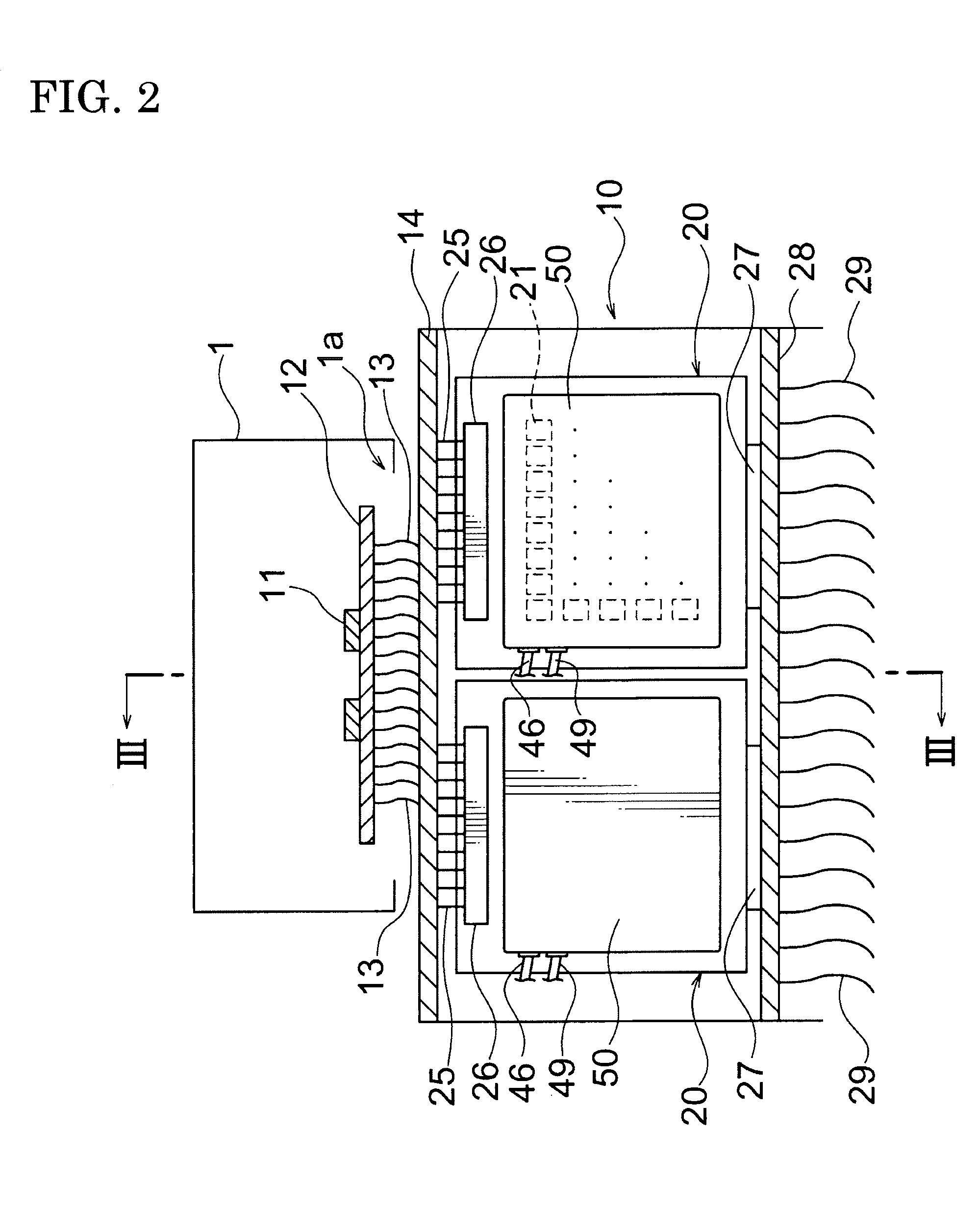
[0068]The socket 11 has a large number of contact...

second embodiment

[0082]FIG. 13 is a cross-sectional view showing a water jacket in the present invention. When the blocks 52 house relatively large sized electronic devices 23B, as shown in FIG. 13, it is also possible to branch the first partitions 52B from the second partitions 52B adjoining the first partitions 52A.

[0083]As shown in FIG. 5, each of the partitions 52 is provided with throttle part 54 of which a flow passage sectional area is smaller than other parts in the channel 51. As shown in FIG. 7, the opening width w of the throttle part 54 is smaller than the length L of the whole of MCM 22A along directions substantially perpendicular to the direction of flow of the coolant (w54 is about the length of the first bare chip 222 along the longitudinal direction of FIG. 7. As shown in FIG. 8, the flow passage sectional area is narrower at the throttle part 54. Note that, in the present embodiment, the nine throttle parts 541 to 549 are referred to all together as the “throttle part 54” while t...


PUM


Abstract

A water jacket includes a channel which accommodates MCM and through which a coolant runs, and the channel has a throttle part of which a flow passage sectional area is smaller than other parts and which is at the upstream of the MCM.

Description

TECHNICAL FIELD[0001]The present invention relates to a water jacket mounted on a board for cooling an electronic device mounted on the board and to an electronic device cooling apparatus and electronic device test apparatus with the same.BACKGROUND ART[0002]In the process of production of various electronic devices such as semiconductor integrated circuit devices (below, also simply referred to as DUTs (devices under test)), an electronic device test apparatus is used to test the DUTs for performance and function. This electronic device test apparatus comprises: a tester body sending a test signal to a DUT and inspecting a response signal; a test head connected to this tester body and having a socket for electrically contacting the DUT; and a handler successively conveying DUTs over the test head and classifying DUTs finished being tested according to test results. Tests by this electronic device test apparatus are conducted in a state with the handler giving the DUT a high tempera...

Claims


Application Information

Patent Timeline
Patent Type & Authority Applications(United States)
IPC IPC(8): H05K7/20
CPCG01R31/2877H01L23/473H01L2924/09701H05K7/20254H01L2924/0002H01L2924/00
Inventor NISHIURA, KOEI
Owner ADVANTEST CORP
Why Eureka
Try Eureka