Measurement of Steam Quality in Steam Turbine

a steam turbine and steam quality technology, applied in the field of steam turbines, can solve the problems of inability to provide a means of measuring steam quality during normal operation of the steam turbine, inability to immediately respond to tracer tests, and inability to measure steam quality

Inactive Publication Date: 2010-10-28
GENERAL ELECTRIC CO
View PDF20 Cites 4 Cited by
  • Summary
  • Abstract
  • Description
  • Claims
  • Application Information

AI Technical Summary

Problems solved by technology

However, current methods of measuring the quality of steam in a steam turbine do not provide a means for measuring steam quality during normal operation of the turbine.
However, the feedback from a tracer test is not immediate and typically the high costs of running such a test prohibits it from being done on a constant basis.
Obviously, this means of measuring steam quality has inherent limitations and does not accurately measure the quality of steam in a system.

Method used


Image

  • Measurement of Steam Quality in Steam Turbine
  • Measurement of Steam Quality in Steam Turbine
  • Measurement of Steam Quality in Steam Turbine

Examples


Embodiment Construction

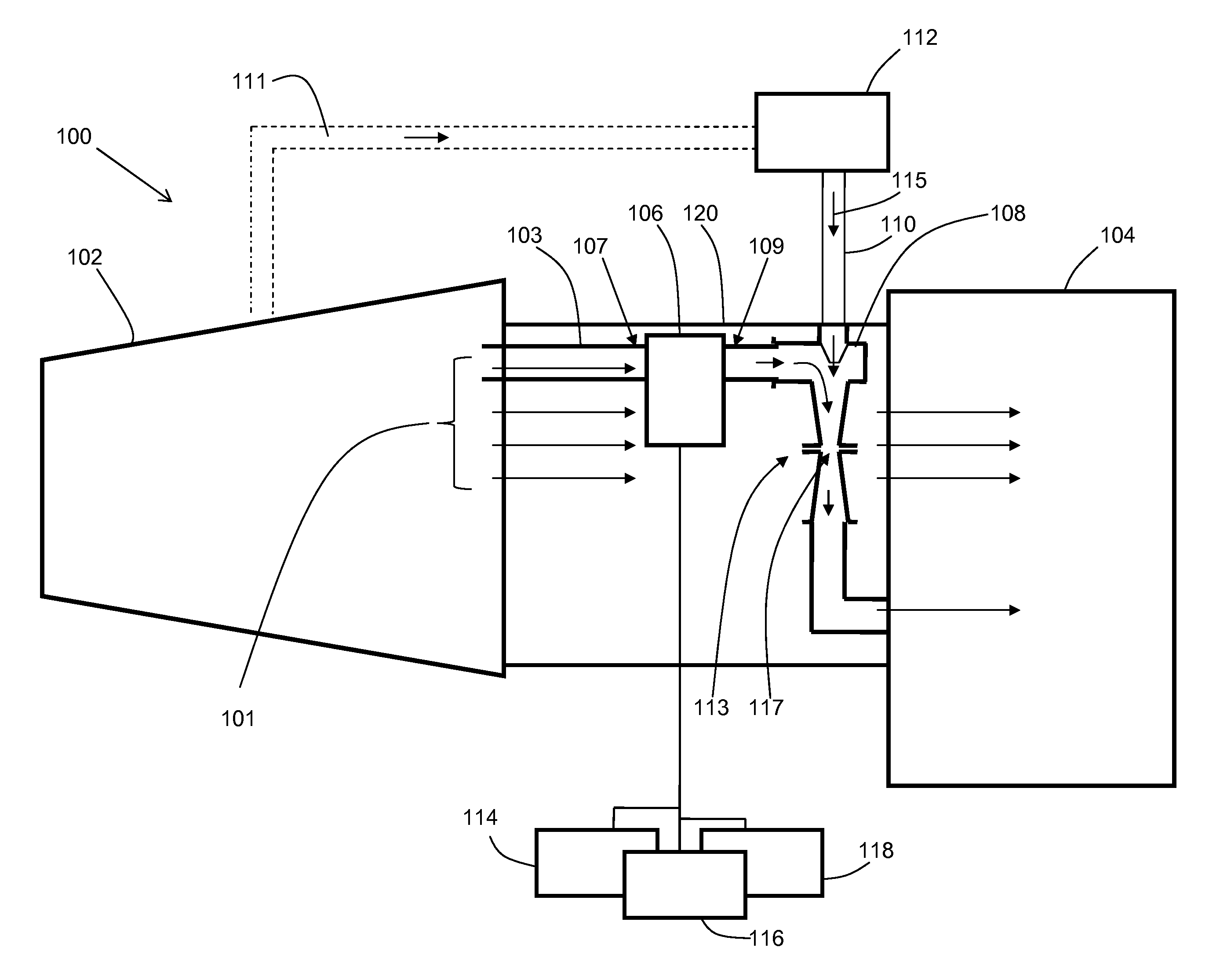
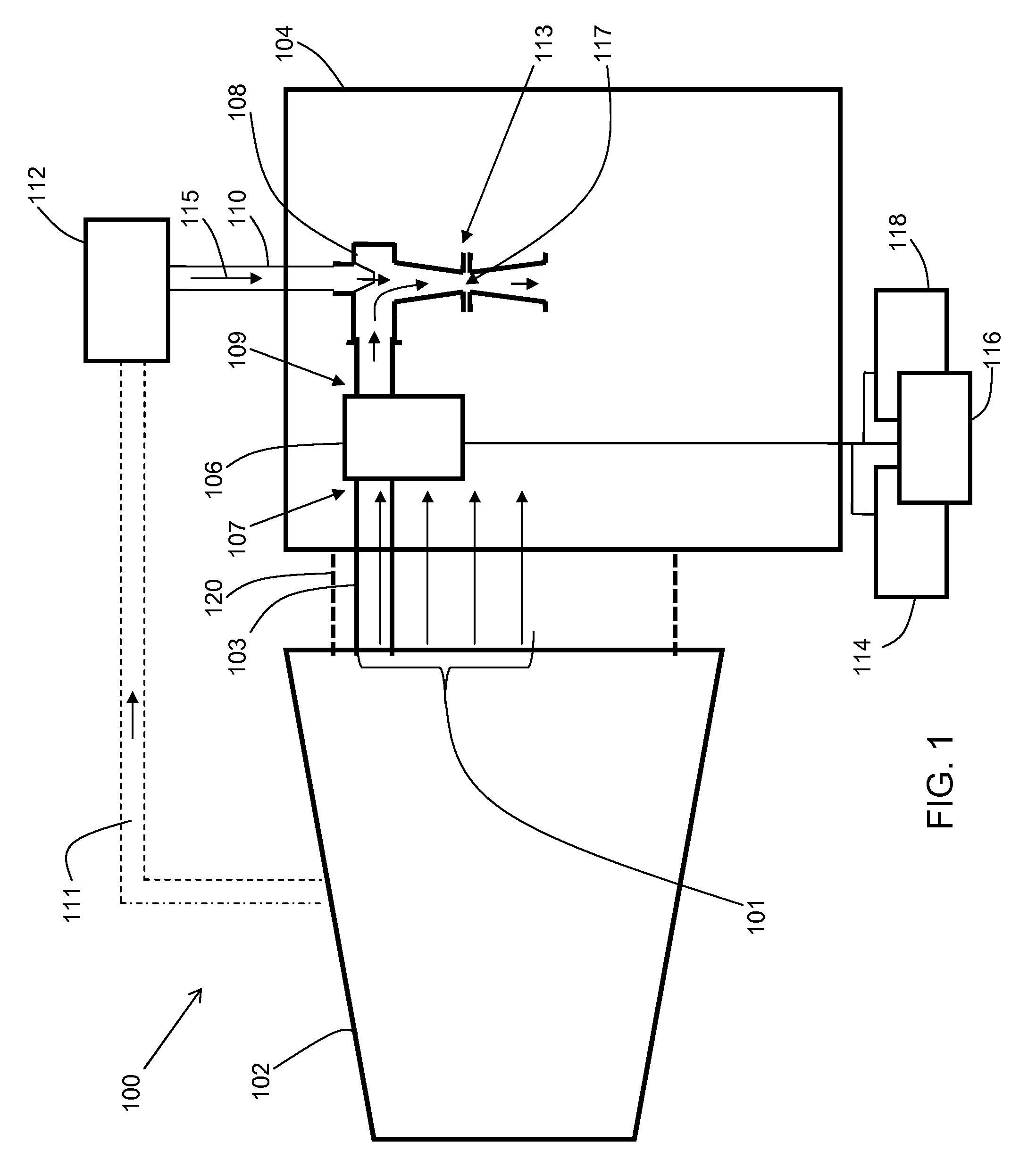
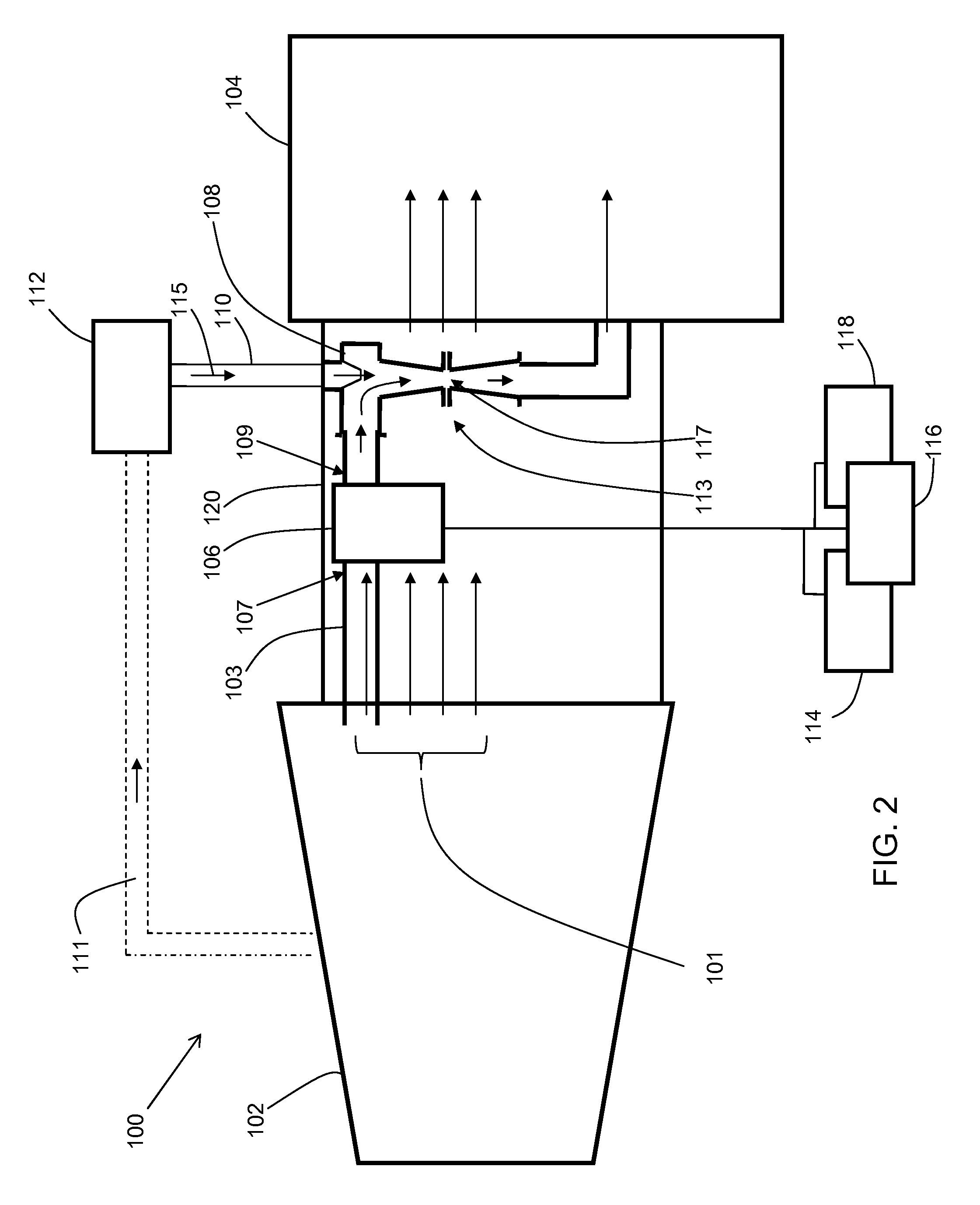
[0010]Turning to FIG. 1, a system 100 for measuring steam quality in a steam turbine 102 according to an embodiment of this invention is shown. System 100 includes a steam quality measurement (SQM) device 106 configured to measure steam quality in steam turbine 102 during operation of steam turbine 102, for example, continuously. A first end 107 of SQM device 106 is coupled to steam turbine 102. As known in the art, steam turbine 102 will emit steam exhaust through an exhaust (not shown). Steam exhaust emitted from steam turbine 102 is illustrated by arrows 101. During operation, exhaust steam 101 will be emitted from steam turbine 102 into condenser 104 to be condensed and recycled for further use in steam turbine 102. Depending on the specific arrangement of steam turbine 102 and condenser 108, there may also be a transition piece 120 between steam turbine 102 and condenser 108. Transition piece 120 can be any shape or material desired, configured to direct steam exhaust 101 from ...


PUM

PropertyMeasurementUnit
pressureaaaaaaaaaa
shapeaaaaaaaaaa
atmospheric pressureaaaaaaaaaa

Abstract

A solution for measuring steam quality in a steam turbine is disclosed. A steam quality measurement (SQM) device and an ejector are coupled to a steam turbine through an appropriate piping configuration to draw steam emitted from the turbine through the SQM device for measurement of the steam quality, for example, continuously, during operation of the turbine.

Description

BACKGROUND OF THE INVENTION[0001]The invention relates generally to steam turbines. More particularly, the invention relates to a solution for measuring steam quality in a steam turbine.[0002]Measurement of the steam quality in a steam turbine is often desired in order to improve the turbine's performance, improve turbine control and plant control (such as tuning condenser performance, heat recovery steam generator (HRSG) adjustments and gas turbine operation). However, current methods of measuring the quality of steam in a steam turbine do not provide a means for measuring steam quality during normal operation of the turbine. For example, one current method, a tracer test, such as described in U.S. Pat. No. 4,788,848, can be performed, which basically involves the injection of a solution into the steam supply. However, the feedback from a tracer test is not immediate and typically the high costs of running such a test prohibits it from being done on a constant basis.[0003]Alternati...

Claims


Application Information

Patent Timeline
Patent Type & Authority Applications(United States)
IPC IPC(8): G01K17/06
CPCF01D21/003F05D2260/601F05D2220/31F01K13/003
Inventor HANNULA, SCOTT VICTORROSSON, RANDY SCOTTWILKES, KEVIN WOOD
Owner GENERAL ELECTRIC CO
Why Eureka
Try Eureka