Storage system for fuels

a technology of condensation system and fuel, which is applied in the direction of liquefaction, lighting and heating apparatus, and discharging methods of containers, etc., can solve the problems of lng to change to vapor, heat can still enter the tank, and natural gas has a lower energy density than traditional fuel, so as to facilitate mixing

Inactive Publication Date: 2018-01-04
ELECTRO-MOTIVE DIESEL
View PDF6 Cites 1 Cited by
  • Summary
  • Abstract
  • Description
  • Claims
  • Application Information

AI Technical Summary

Benefits of technology

[0005]In one aspect, the disclosure is directed towards a condensation system for a reservoir that is configured to store a fuel cryogenically. A portion of the fuel exists as a boil-off gas within the reservoir with a first vapor quality. The condensation system includes an absorption unit, a distillation unit, and a cooling circuit. The absorption unit is fluidly coupled to the reservoir. The absorption unit is configured to receive a refrigerant and the boil-off gas and facilitate a mixing between the boil-off gas and the refrigerant to form a liquid solution. The distillation unit is fluidly coupled to the absorption unit and is adapted to receive

Problems solved by technology

Natural gas, however, has a lower energy density than traditional fuels such as diesel and gasoline.
However, some heat can still enter the tank because of an imperfect or worn out tank insulation, causing some of the LNG to change to vapor.
The increasing pressure, if left unchecked, may damage the tank and can even cause the tank to explode

Method used


Image

  • Storage system for fuels
  • Storage system for fuels
  • Storage system for fuels

Examples


Embodiment Construction

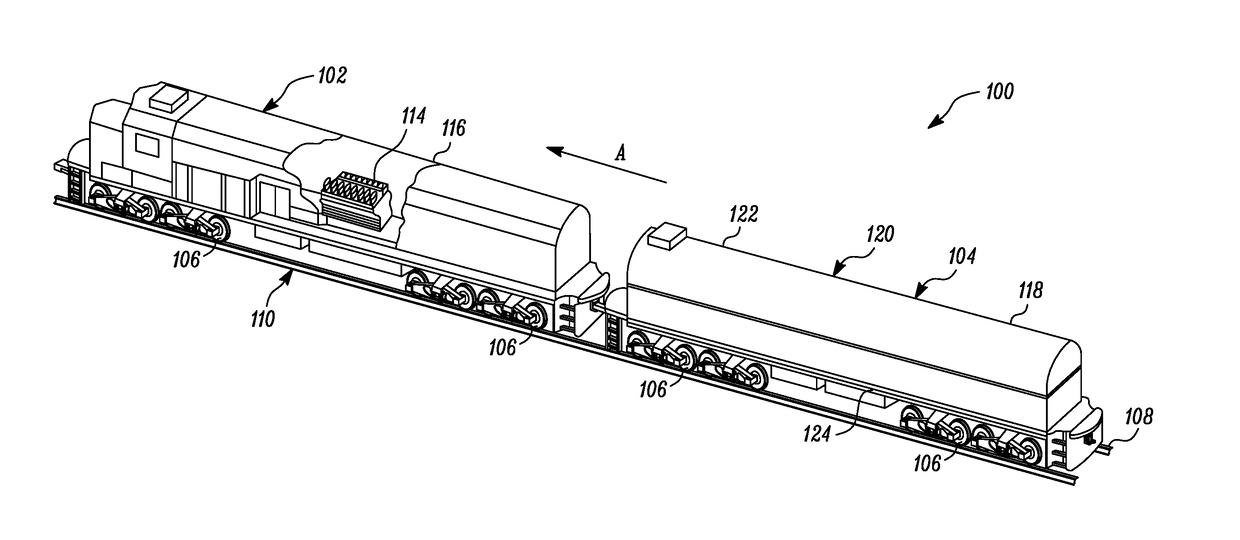
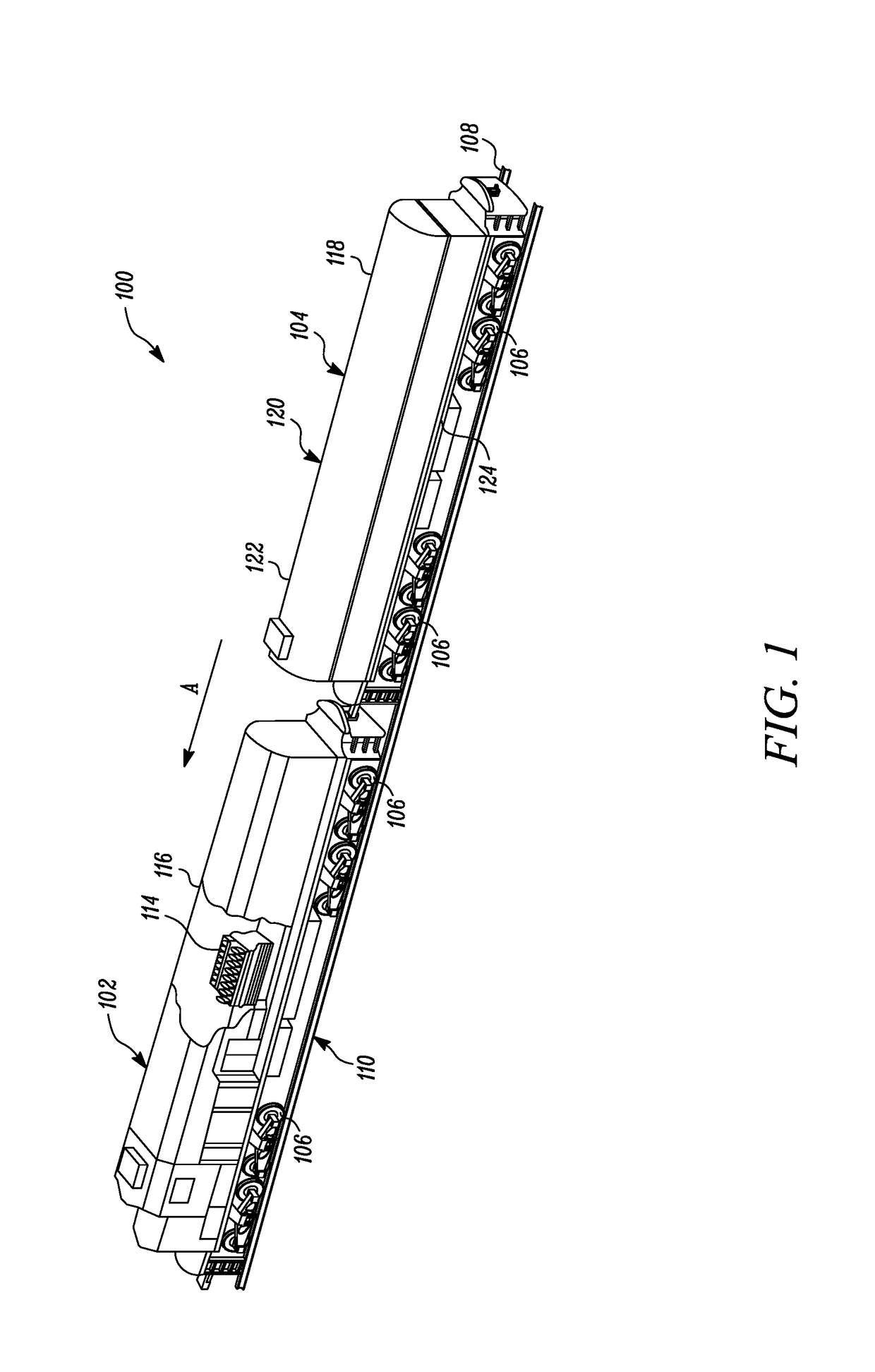
[0011]Referring to FIG. 1, a machine 100 is disclosed. The machine 100 is a locomotive system. The machine 100 includes an engine assembly 102 and a rolling stock 104. In an embodiment, the machine 100 includes a single engine assembly, although it is possible to have multiple engine assemblies connected to each other to facilitate machine movement. As an example, the machine 100 may include a train propelled by a single engine assembly or by multiple engine assemblies. Further, other known arrangements of locomotives may also be contemplated. A number of wheels 106 are positioned throughout a length of the machine 100 in a known manner. The wheels 106 engage tracks 108 of an associated railroad 110, supporting and facilitating traversal of the machine 100 over an expanse of the railroad 110. Although aspects of the present disclosure are applicable to a locomotive system, aspects of the present disclosure are applicable to various other machines and environments.

[0012]The engine as...


PUM


Abstract

A condensation system for a reservoir, which stores fuel cryogenically, is disclosed. A portion of the fuel exists as a boil-off gas with a first vapor quality. The condensation system includes an absorption unit coupled to the reservoir and is configured to receive and mix the boil-off gas with a refrigerant, forming a liquid solution. A distillation unit is coupled to the absorption unit to receive the liquid solution at a supplemented pressure, and is configured to separate the fuel to a gaseous state from the liquid solution. Further, a cooling circuit is configured to receive the fuel in the gaseous state from the distillation unit at the supplemented pressure and a supplemented temperature, and deliver the fuel to the reservoir at a lower pressure and a temperature, with a vapor quality lower than the first vapor quality.

Description

TECHNICAL FIELD[0001]The present disclosure relates to a condensation system for fuels which may exist as a boil-off gas within reservoirs. More particularly, the present disclosure relates to a condensation system that is based on a vapor absorption refrigeration cycle.BACKGROUND[0002]Natural gas has been well received as a plentiful, low emission, and viable alternative to traditional fuels such as diesel. Natural gas, however, has a lower energy density than traditional fuels such as diesel and gasoline. As a result, mobile machines, such as locomotive systems, generally use liquefied natural gas (“LNG”) as fuel to power a locomotive movement. To maintain natural gas in liquid form at atmospheric pressure, LNG's temperature must remain about −160° Celsius. Mobile machines, such as locomotives, utilizing LNG as a fuel, therefore, typically store LNG in insulated tanks. However, some heat can still enter the tank because of an imperfect or worn out tank insulation, causing some of ...

Claims


Application Information

Patent Timeline
IPC IPC(8): F25J1/00F17C13/08F17C3/02F17C9/00
CPCF25J1/0025F17C3/022F17C9/00F17C2270/0581F17C2221/035F17C2260/031F17C13/083F17C2201/035F17C2201/054F17C2203/03F17C2203/0629F17C2221/033F17C2223/0161F17C2223/0169F17C2223/033F17C2265/033F17C2265/037F17C2270/0173
Inventor FOEGE, AARON GAMACHEHANNINK, VERONICA ANNE
Owner ELECTRO-MOTIVE DIESEL
Why Eureka
Try Eureka