Radiofrequency transmission system

Active Publication Date: 2010-10-28
COMMISSARIAT A LENERGIE ATOMIQUE ET AUX ENERGIES ALTERNATIVES
View PDF9 Cites 9 Cited by
  • Summary
  • Abstract
  • Description
  • Claims
  • Application Information

AI Technical Summary

Benefits of technology

[0016]The object of the present invention is to provide a solution to the above-mentioned problems by proposing a radiofrequency transmission system which has relatively compact overall dimensions, is rapidly reconfigurable in order to operate using several transmission formats, allows communication over a wide power range and performs well in terms of power consumption.

Problems solved by technology

Nevertheless, a radio transmitter which is suitable for transmitting in accordance with a particular standard is not generally suitable for transmitting according to another standard.
But the polar loop cannot transmit signals with a bandwidth larger than EDGE signals.
Such terminals are therefore bulky and poorly optimised.
In addition, the speed of changeover from one type of transmission to another type of transmission is limited, using a terminal of this type for opportunistic use of radiofrequency spectrum is therefore difficult to envisage.
Thus, to the extent that the devices in which they are fitted are frequently portable, one important criterion is their power consumption because this has a direct influence on the device's battery life.
However, generally speaking, non-constant amplitude signals or signals having a variable envelope impose constraints on the type of amplifier which can be used.
Unfortunately, linear amplifiers perform less well in terms of power consumption than non-linear amplifiers.
Such components are inherently relatively bulky and perform poorly in the main and are therefore unsuitable for use in applications in mobile terminals.

Method used


Image

  • Radiofrequency transmission system
  • Radiofrequency transmission system
  • Radiofrequency transmission system

Examples


first embodiment

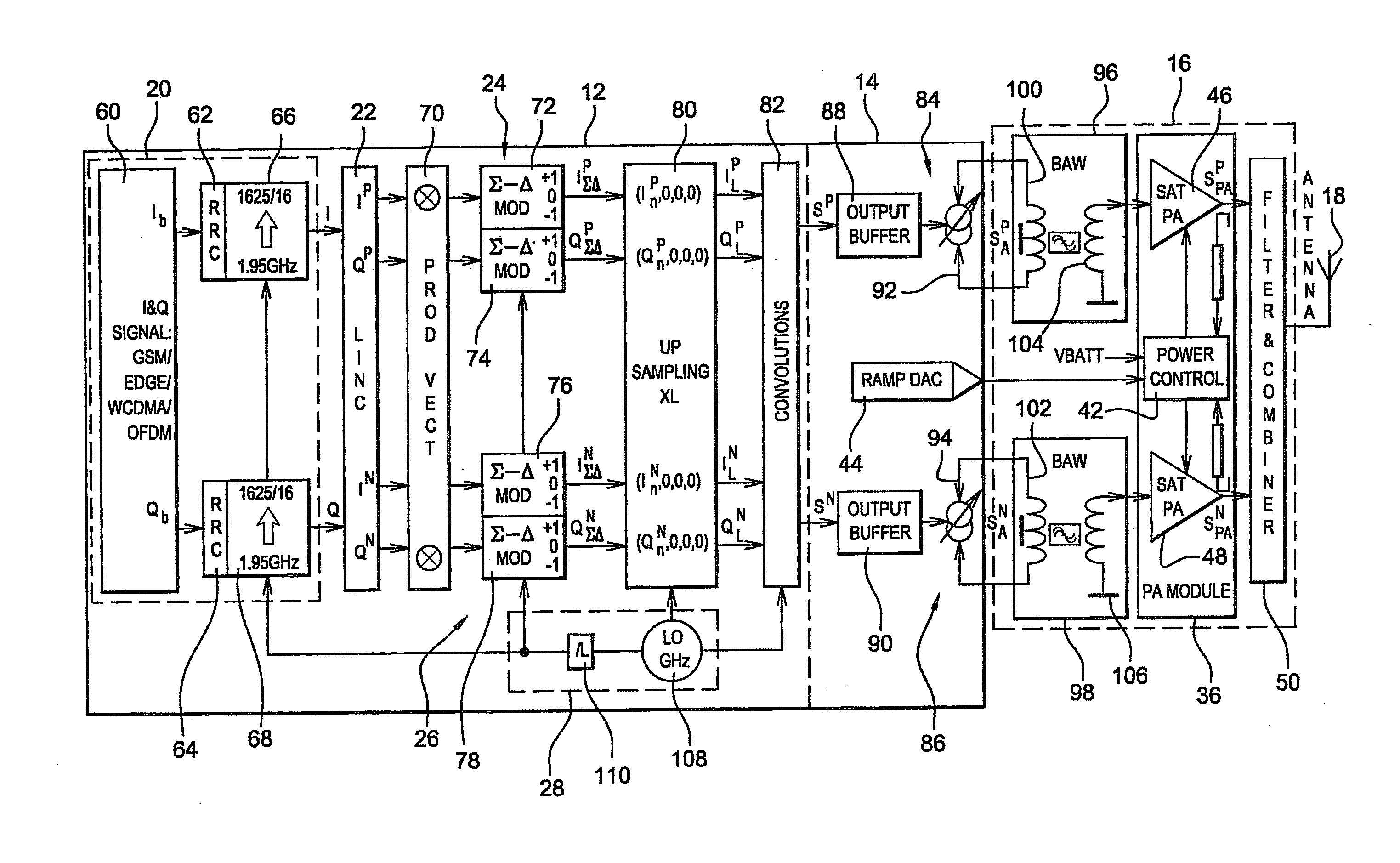
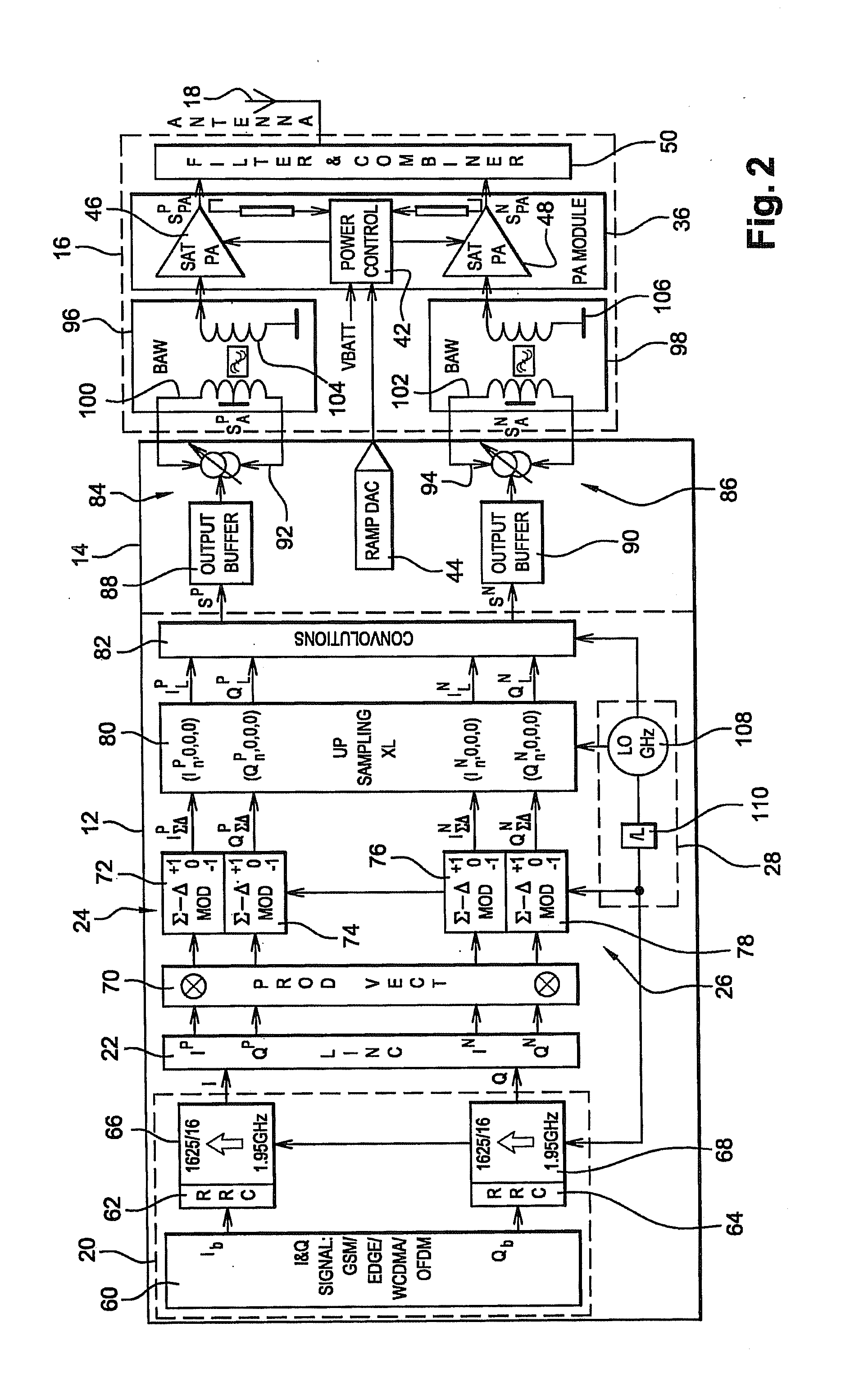
[0083]FIG. 2 illustrates the system according to the invention.

[0084]According to this first embodiment, module 20 for producing the complex digital signal S=I+jQ comprises a digital signal generator 60 which generates a complex digital signal Sb=Ib+jQ in accordance with the selected transmission format. Quadrature digital signals Ib and Qb are quantised on N bits, for example on six, eight or ten bits, and sampled at a baseband frequency f1. The useful information in signals Ib and Qb therefore occupies a frequency band which is centred either side of the zero frequency.

[0085]Module 20 optionally comprises two Root Raised Cosine (RRC) filters 62, 64 which are connected to generator 60 and receive signals Ib and Qb respectively. RRC filters 62, 64 make it possible to limit spectral spreading of the signal to the width of the envisaged channel.

[0086]Module 20 also comprises two over-samplers 66, 68 which are connected to RRC filters 62, 64 respectively and produce the real and imagin...

second embodiment

[0109]FIG. 3 illustrates the system according to the invention.

[0110]This second embodiment differs from that described in relation to FIG. 2 in that the real part of each signal SLINCP=IP+jQP and SLINCN=jQN is selected on the output of transformation module 22, for example by channel selector 70 which is modified in order to implement this function.

[0111]Two signals RP and RN are produced by channel selector 70, so each digital processing pathway only comprises a single bandpass sigma-delta filter 72, 74 which operates in bandpass mode.

[0112]Channel selector 70 forms, on demand, the vector product of the real parts IP and IN of each of the complex digital signals SLINCP and SLINCN obtained from transformation module 22 by a programmable-amplitude phasor whose frequency equals the difference between the frequency of the desired transmission channel fCH and the frequency of the centre channel fC to which the mid-band frequency fBP of sigma-delta filter 72, 74 is also added.

[0113]Note...


PUM


Abstract

The invention relates to a radiofrequency transmission system comprising: means of producing a complex digital signal quantised on N bits; means of transforming the complex digital signal into two complex digital signals with an identical and constant envelope that are phase-shifted with respect to one another; a digital processing pathway associated with each of the two complex digital signals with a constant envelope and comprising at least some filtering means of the sigma-delta type for quantising on M bits signals travelling in the processing pathway, M being less than N; digital-to-analogue conversion means for converting the outputs of the digital processing pathways into analogue signals; means of selectively filtering (of the bandpass type) the analogue signals in a predetermined transmission frequency band; means of amplifying the filtered analogue signals; and means of recombining the amplified analogue signals.

Description

DOMAIN OF THE INVENTION[0001]The present invention relates to the field of radiofrequency transmitters, especially those used in wireless communication terminals such as mobile telephones for example.[0002]The invention relates, more especially, to reconfigurable radiofrequency transmitters which are capable of transmitting over a wide power range and using several transmission formats.DESCRIPTION OF THE PRIOR ART[0003]In the field of wireless radio communication, there are numerous communication formats which use electromagnetic waves in the radiofrequency band such as the UHF, GSM, EDGE, WCDMA, 3G, etc. standards. Each of these standards is associated with a particular transmission frequency band (one talks of the UHF band, GSM band, 3G band, etc. for example).[0004]Nevertheless, a radio transmitter which is suitable for transmitting in accordance with a particular standard is not generally suitable for transmitting according to another standard. For example, the architecture of a...

Claims


Application Information

Patent Timeline
IPC IPC(8): H04L27/00
CPCH03F1/0294H04L27/362H03F3/211H03F3/24H03F2200/331H03F2200/336H03F2200/451H03F2200/534H03F2200/537H03F2203/21112H03F2203/21157H04B1/0483H04B2001/045H04L27/2626H03F1/32H03F1/02
Inventor WURM, PATRICKCLAIRESHIRAKAWA, ALEXANDRE
Owner COMMISSARIAT A LENERGIE ATOMIQUE ET AUX ENERGIES ALTERNATIVES
Why Eureka
Try Eureka