Method for operating a drive train

Inactive Publication Date: 2010-10-28
SCHAEFFLER TECH AG & CO KG
View PDF3 Cites 30 Cited by
  • Summary
  • Abstract
  • Description
  • Claims
  • Application Information

AI Technical Summary

Benefits of technology

[0007]By linking the characteristic numbers of the damping device, which, for instance, result from non-linear stiffness and friction behavior, with the differential angle between the input part and the output part, a focused selection can lead to the characteristic data based on the differential rotation angle, so that, in the area of the differential angle selected accordingly in a simple manner, corresponding non-linear associations between the disturbance torque to be determined and the characteristic data can be determined and computed as well, so that determining disturbance torque and correction of load torque or other variables, such as engine torque and the likes, is possible in real time. Only the changing variables of the speeds of the input- and output part are acquired in the process. Speed sensors like incremental transducers attached to the input- and output part can serve this purpose if they feature a definite zero point, in that a gap is provided in the sending ring, for instance.

Problems solved by technology

Moreover, changeover friction can occur during the differential angle's change of direction.
Furthermore, when several or all the windings of an arc spring go solid, the stiffness of the damping device of the dual mass flywheel can change and upon increase of the rotation speed of the dual mass flywheel, the speed-dependent friction can occur owing to centrifugal support of the windings of the arc springs on the input part.

Method used


Image

  • Method for operating a drive train
  • Method for operating a drive train
  • Method for operating a drive train

Examples


Embodiment Construction

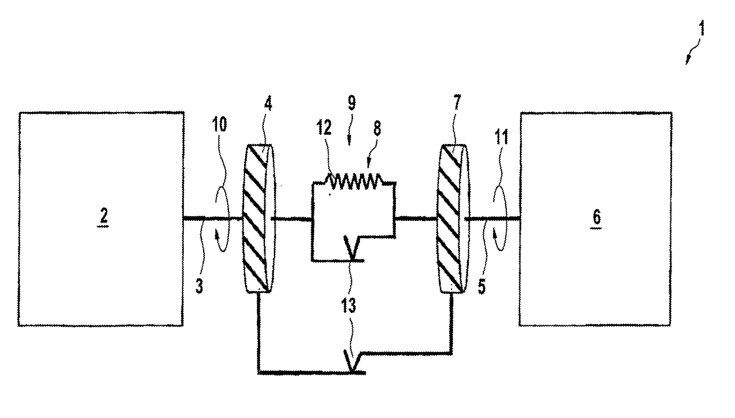
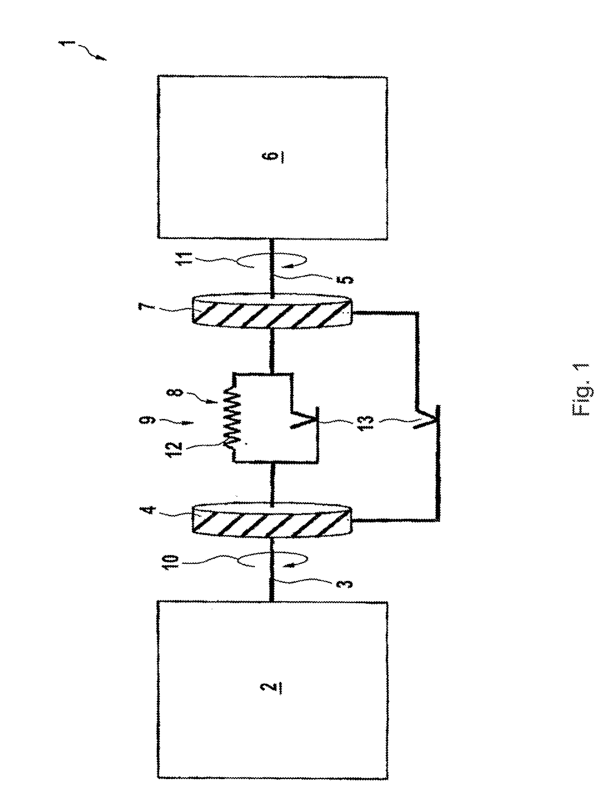
[0018]FIG. 1 shows the schematically depicted drive train 1 with the internal combustion engine 2 and the input part 4 connected with the crankshaft 3 of the internal combustion engine 2, the output part 7 connected with the transmission input shaft 5 of the transmission 6 and the damping device 8 of the dual mass flywheel 9 interposed in between. Because of the damping device 8 equipped by different friction control devices 13 and energy accumulators like arc springs 12, hysteresis-laden damping of torsional vibrations of the drive train 1 is achieved. As a result, an exact calculation of the engine torque Mengine of the internal combustion engine 2 and of the load torque Mload acting on the transmission input shaft 5 is not possible without considering disturbance torque MF caused by the hysteresis in the dual mass flywheel. The calculation equation for the engine torque Mengine and the load torque in dependence on the disturbance torque MF are as follows:

Mengine=MF+MR·sign(Δω)+J1...


PUM


Abstract

A method for operating a drive train in a motor vehicle with a dual mass flywheel driven by an internal combustion engine via a crankshaft and at least a transmission input shaft of a transmission that can be coupled with an output part of the dual mass flywheel. Between the input part and output part a hysteresis-laden damping device is effective, which influences engine torque output from the internal combustion engine and load torque transmitted to at least a transmission input shaft through the hysteresis characteristic. To eliminate the disturbances caused by the dual mass flywheel a state model constantly determines rotation speeds of the input part and of the output part and depending on a differential angle determined from the rotation speeds and from the characteristic numbers of the damping device, a characteristic disturbance torque for influencing at least the load torque is determined in real time.

Description

CROSS-REFERENCE TO RELATED APPLICATIONS[0001]This application claims priority from German Patent Application No. 10 2009 019 072.4, filed Apr. 27, 2009, which application is incorporated herein by reference in its entirety.FIELD OF THE INVENTION[0002]The invention relates to a method for controlling a dual clutch transmission with two drive trains that can be coupled with an internal combustion engine.BACKGROUND OF THE INVENTION[0003]By considering the dynamics of dual mass flywheels, it is possible to estimate at least the torque with the help of primary- and secondary side rotation speeds during the operation of the drive train. Such estimated torque can be used for example as a controlling or regulating variable in order to control automated transmissions, for instance automatic shifting devices, automated manual transmission or twin-clutch transmission.[0004]To determine the behavior of dual mass flywheels, the rotation speeds of primary and secondary speed transducers are evalu...

Claims


Application Information

Patent Timeline
IPC IPC(8): B60W30/18B60W10/06G06F19/00B60W10/10
CPCB60K6/105Y10T477/688Y10T477/675Y02T10/6204Y02T10/62
Inventor WINKLER, THOMASDAGDAN, ALI
Owner SCHAEFFLER TECH AG & CO KG
Why Eureka
Try Eureka