Stent Delivery System Having Stent Securement Apparatus
What is Al technical title?
Al technical title is built by PatSnap Al team. It summarizes the technical point description of the patent document.
a technology of stent and securement device, which is applied in the field of assembly and method of delivering and deploying an inflation expandable stent, can solve the problems of stent slippage and dislocation from the desired position, and achieve the effect of reducing the diameter of the sten
Inactive Publication Date: 2010-10-28
BOSTON SCI SCIMED INC
View PDF99 Cites 54 Cited by
Summary
Abstract
Description
Claims
Application Information
AI Technical Summary
This helps you quickly interpret patents by identifying the three key elements:
Problems solved by technology
Method used
Benefits of technology
[0014]An alternative embodiment of present invention is also an assembly for delivery and deployment of an inflation expandable stent within a vessel. The assembly comprises a catheter, an expandable balloon mounted on the catheter, a corrugated tubing mounted on the catheter beneath or within the balloon, and a stent mounted on the balloon. The catheter has proximal and distal ends. The stent is inflation expandable from a delivery diameter to a deployment diameter. The delivery diameter is reduced from the deployment diameter for conforming the stent to the catheter. The stent, in its delivery diameter, is coaxially mounted on the catheter near the catheter distal end. The expandable balloon is coaxially mounted on the catheter axially within the stent. The balloon is designed and adapted for expansion of the stent from the delivery diameter to the deployment diameter upon application of fluid deployment pressure to the balloon. The corrugated tubing is mounted and adhered coaxially onto the catheter and is situated between the balloon and the catheter itself When the stent is crimped and loaded onto the balloon, the balloon is situated therefore between the stent and the corrugated tubing. The tubing is preferably essentially equal to the length of the stent and the stent is positioned on the assembly essentially co-extensive with the tube component. The tubing on the catheter effectively holds the stent in place, takes up the slack due to recoil and protects the balloon material from being damaged during crimping.
Problems solved by technology
During delivery, the stent can thus tend to slip and dislocate from its desired position on the catheter or even become separate from the catheter, requiring further intervention by the physician.
Method used
Image
Click on the blue label to locate the original text in one second.
Reading with bidirectional positioning of images and text.
Examples
Embodiment Construction
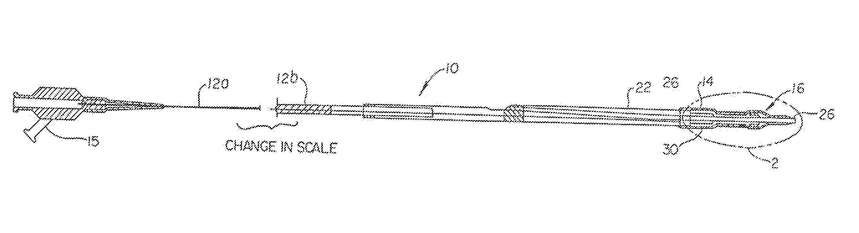
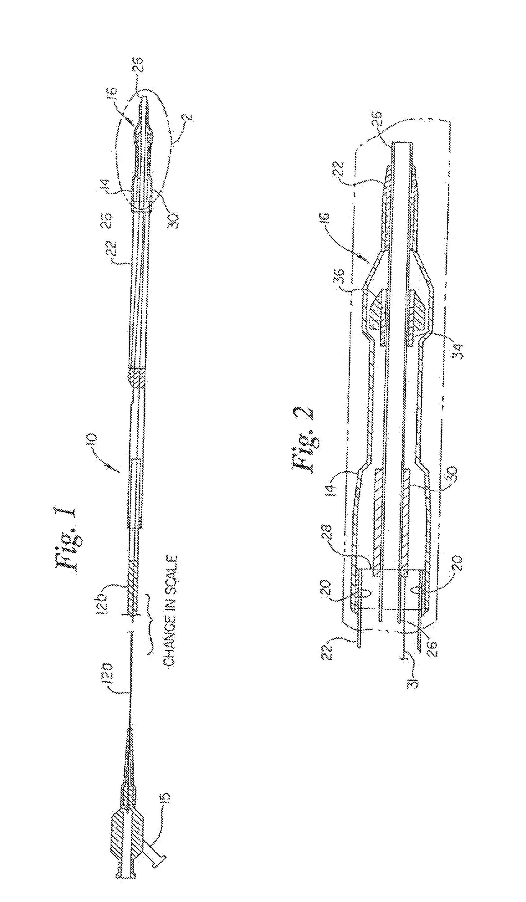
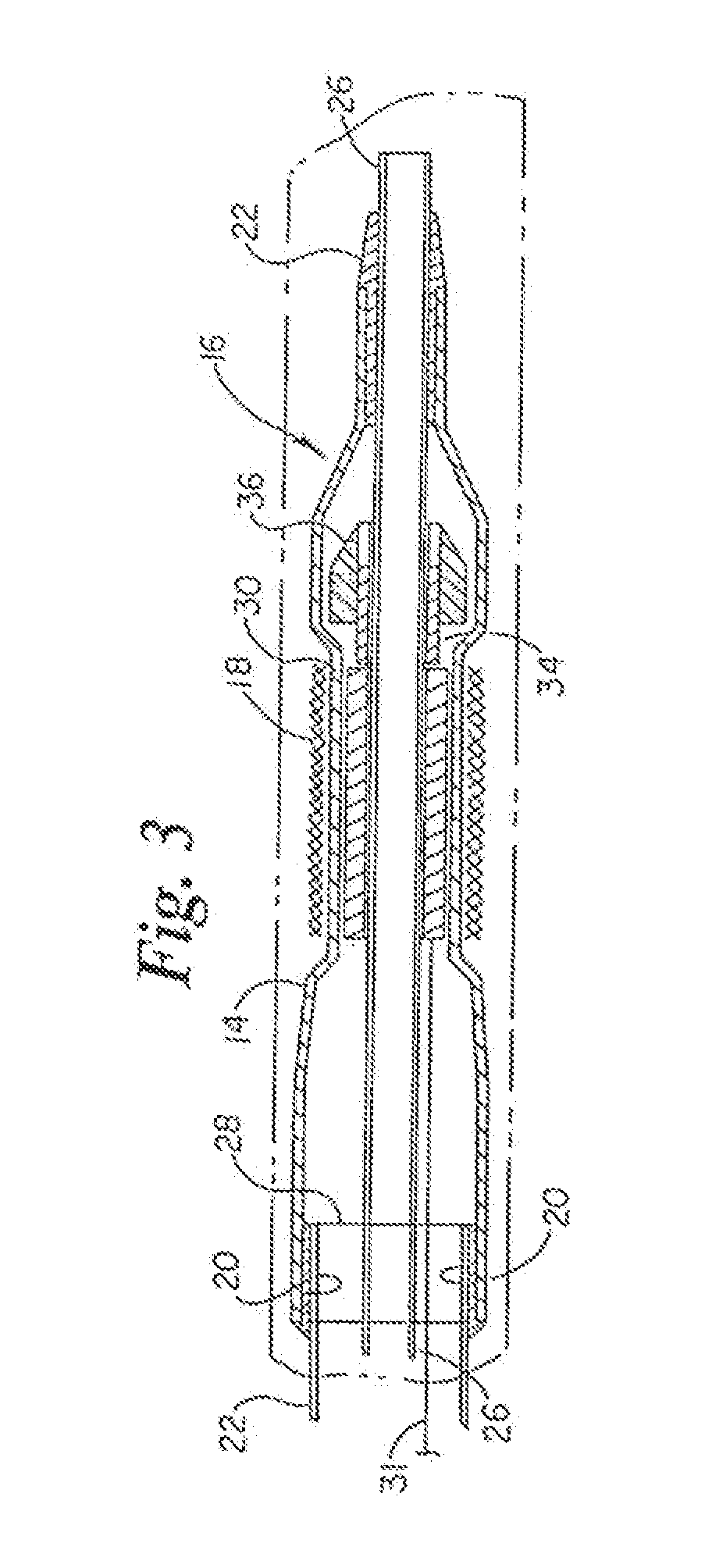
[0063]The present invention relates to stent securement devices, most notably positioned between the balloon and the inner shaft of the catheter. Individual elements of the below disclosed embodiments are generally interchangeable if desired. Referring to FIGS. 1-4 an angioplasty and stent delivery catheter system generally indicated at 10 includes a balloon catheter 12 having a balloon 14 on a distal end portion generally indicated at 16. FIG. 1 shows a proximal portion of the catheter at 12a and a distal portion 12b in enlarged view. FIGS. 2 and 3 show the distal end portion 16 in an even more enlarged view. The illustrative catheter 12 is of the type known as a rapid exchange or single operator catheter. However, other types of catheters may be used, such as over the wire and fixed wire types. The balloon 14 is fixed to the catheter 12 by standard means. The balloon is shown in its contracted state in. A stent 18 is fixed about the balloon by crimping thereto. The stent has a lar...
PUM
Abstract
A system / assembly for delivery and deployment of an inflation expandable stent within a vessel, comprising a catheter having proximal and distal ends; a stent, inflation expandable from a delivery diameter to a deployment diameter, such that the delivery diameter is reduced from the deployment diameter for conforming the stent to the catheter, such that the stent, in its delivery diameter, is coaxially mounted on the catheter near the catheter distal end; an expandable inflation means coaxially mounted on the catheter axially within the stent, for expansion of the stent from the delivery diameter to the deployment diameter upon application of fluid deployment pressure to the inflation means; and a securement component coaxially mounted on the catheter, axially within the expandable inflation means, the securement component designed and adapted to provide a securement pressure to the stent in the delivery diameter to maintain the stent in position on the catheter during delivery to the deployment site.
Description
CROSS-REFERENCE TO RELATED APPLICATIONS[0001]The present application is a continuation of U.S. Ser. No. 10 / 737,497, filed Dec. 16, 2003 and issued as U.S. Pat. No. 7,670,364, which is a continuation of U.S. Ser. No. 09 / 794,648, filed Feb. 27, 2001 and issued as U.S. Pat. No. 6,663,660, which is a continuation of U.S. Ser. No. 09 / 418,277, filed Oct. 14, 1999 and issued as U.S. Pat. No. 6,203,558, which is a continuation of U.S. Ser. No. 08 / 916,544, filed Aug. 22, 1997 and issued as U.S. Pat. No. 5,968,069, which is a Continuation-in part application based on U.S. Ser. No. 08 / 807,791, filed Feb. 28, 1997 and issued as U.S. Pat. No. 6,077,273, U.S. Ser. No. 08 / 702,150, filed Aug. 23, 1996 and issued as U.S. Pat. No. 6,007,543, U.S. Ser. No. 08 / 697,453, filed Aug. 23, 1996 abandoned, and U.S. Ser. No. 08 / 701,979, filed Aug. 23, 1996 and issued as U.S. Pat. No. 6,395,008, all of which are incorporated by reference in their entirety.FIELD OF THE INVENTION[0002]This invention relates to an...
Claims
Application Information
Patent Timeline
Application Date:The date an application was filed.
Publication Date:The date a patent or application was officially published.
First Publication Date:The earliest publication date of a patent with the same application number.
Issue Date:Publication date of the patent grant document.
PCT Entry Date:The Entry date of PCT National Phase.
Estimated Expiry Date:The statutory expiry date of a patent right according to the Patent Law, and it is the longest term of protection that the patent right can achieve without the termination of the patent right due to other reasons(Term extension factor has been taken into account ).
Invalid Date:Actual expiry date is based on effective date or publication date of legal transaction data of invalid patent.
Patent Type & Authority Applications(United States)
Inventor DUSBABEK, ANDREW J.ELLIS, LOUIS G.LARSON, CHRISTOPHER R.BROWN, TERRY V.EUTENEUER, CHARLES L.MERTENS, STEVEN P.MATTISON, RICHARD C.BLAESER, DAVID J.LORENTZEN CORNELIUS, LINDA R.WILLARD, MARTIN R.DI CAPRIO, FERNANDONORDIN, STANLEY A.