Method and device to regulate an automated manipulator

a multi-axis, manipulator technology, applied in the direction of programmed manipulators, welding monitoring devices, welding electric supplies, etc., can solve the problems of reducing the quality of the welding spot to the point of failure, damage to the module and one of the electrodes, and affecting the response of automated manipulators, so as to improve the response of the manipulator

Active Publication Date: 2010-10-28
KUKA ROBOTER
View PDF12 Cites 17 Cited by
  • Summary
  • Abstract
  • Description
  • Claims
  • Application Information

AI Technical Summary

Benefits of technology

[0009]An object of the present invention is to improv

Problems solved by technology

However, if a desired position is not reached—for example due to an obstacle or an inaccurate environment modeling in the path plan—a pure position regulation increases the drive forces until either manipulated variable limits are exceeded—which leads to the deactivation of the controller—or the robot forcibly approaches the desired position, and thereby possibly damages an obstacle, a component, a tool or itself.
However, if the component is not in the position on which the welding pose is based in the planning, but rather is shifted in the closing direction of the electrode holder, a merely position-regulated robot would forcibly push the welding electrodes into the predetermined positions and thereby damage the module and one of the electrodes, while the other electrode possibly has no contact with the component.
Even if no damage occurs, impermissible forces that could reduce the quality of the welding spot to the point of failure would occur.
Due to the task-specific rigidity and flexibility ten

Method used


Image

  • Method and device to regulate an automated manipulator
  • Method and device to regulate an automated manipulator
  • Method and device to regulate an automated manipulator

Examples


Embodiment Construction

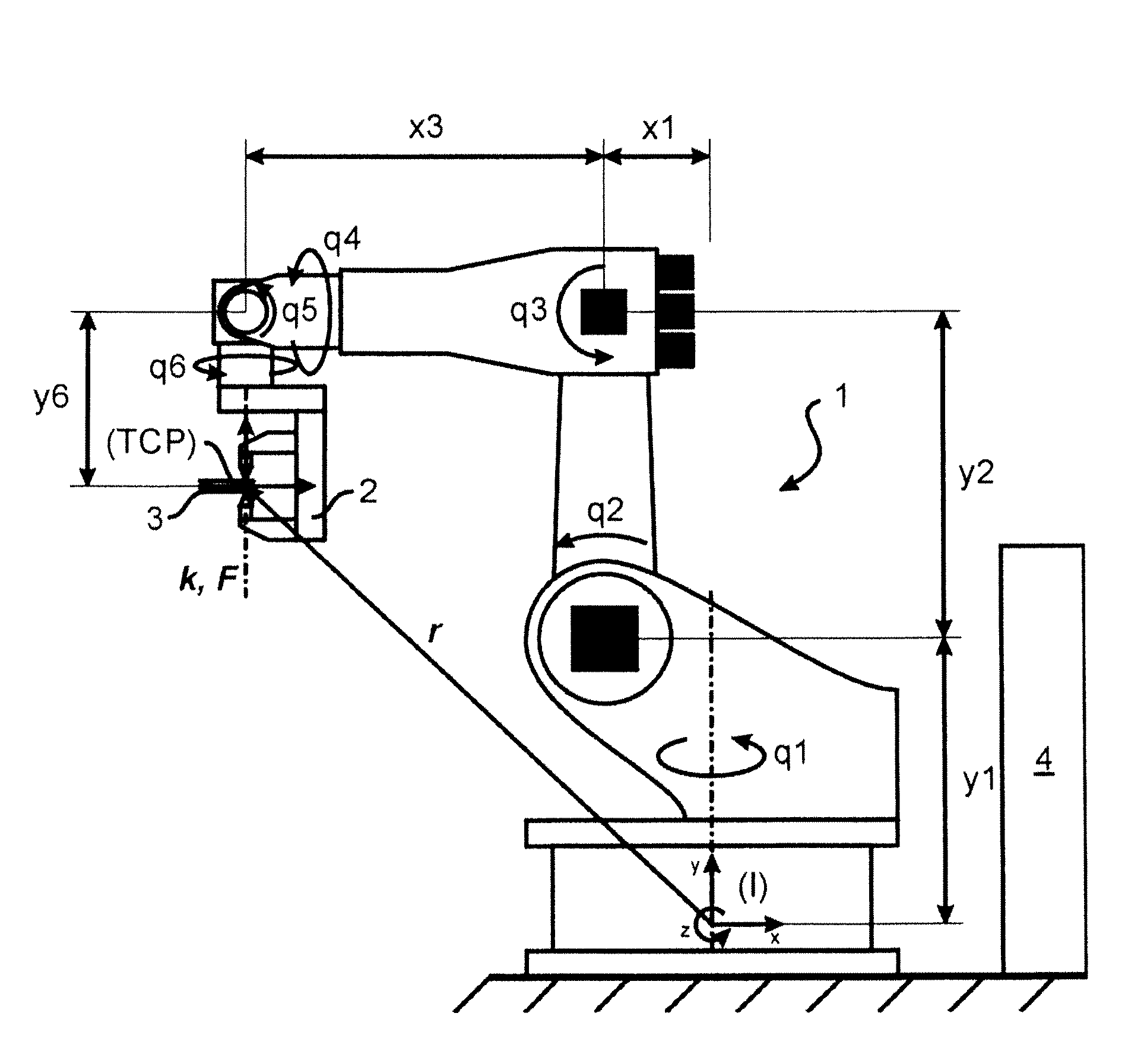
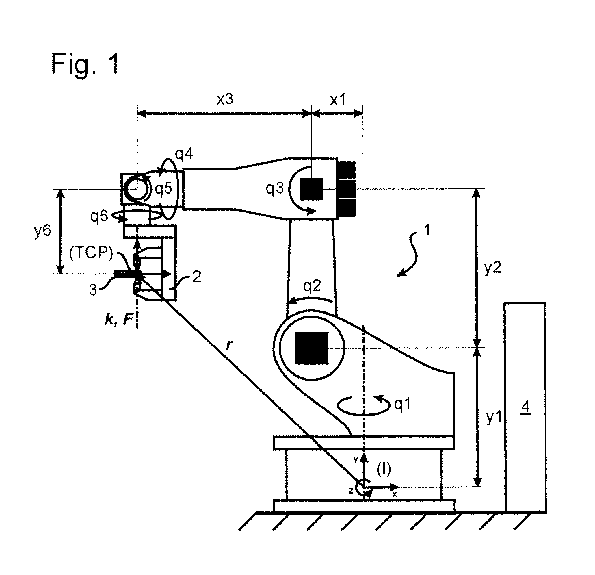
[0031]FIG. 1 shows a six-axis articulated arm robot 1 in a base position in which its six axes or, respectively, joint angles q1, q2, . . . , q6 exhibit a value of zero. For simplification it is assumed that no movement occurs in the axes 1, 4 and 6, such that only a planar movement and the joint coordinates q2, q3 and q5 are considered in the following that define the corresponding rotation positions of the actuation motors via the respective gearing conversions. In the fixed-base inertial system I, the vector x of the tool reference system TCP of an electrode holder 2 that should spot-weld two plates 3 with the axis intervals x1, . . . , y6 drawn in FIG. 1 then reads:

x=x(q)=[rxryϕ]=[-x1-y2·sin(q2)-x3·cos(q2+q3)+y6·sin(q2+q3+q5)y1+y2·cos(q2)-x3·sin(q2+q3)-y6·cos(q2+q3+q5)q2+q3+q5](1)

with the components rx, ry of the spatial vector r relative to the TCP and the EULER angle φ around the z-axis. In the base pose shown in FIG. 1, the Jacobian matrix locally reads:

J(q=0)=∂x∂qq=0=[-y2+y6...


PUM


Abstract

A method for regulation of a multi-axis automated manipulator, in particular of a robot, includes flexible regulation of at least one guide axis, and rigid regulation of at least one additional axis, and determining a desired value of the at least one additional axis on the basis of a real value of the guide axis.

Description

BACKGROUND OF THE INVENTION[0001]1. Field of the Invention[0002]The present invention concerns a method and a device to regulate a multi-axis manipulator, in particular a robot.[0003]2. Description of the Prior Art[0004]Modern industrial robots are predominantly position-regulated. For this purpose, desired joint positions are generated in an interpolator and supplied to individual joint regulators in the individual actuators of the robot. However, if a desired position is not reached—for example due to an obstacle or an inaccurate environment modeling in the path plan—a pure position regulation increases the drive forces until either manipulated variable limits are exceeded—which leads to the deactivation of the controller—or the robot forcibly approaches the desired position, and thereby possibly damages an obstacle, a component, a tool or itself.[0005]An illustrative example is spot welding with an electrode holder. The electrode holder should be pressed with a predetermined cont...

Claims


Application Information

Patent Timeline
IPC IPC(8): B25J9/00G05B19/04G06F19/00
CPCB23K11/25B25J9/1633B23K11/31B25J9/1635B25J9/1653B25J9/1674
Inventor HAGENAUER, ANDREAS
Owner KUKA ROBOTER
Why Eureka
Try Eureka