
Ultrasound multiphase fraction meter and method for determining phase fractions in a multiphase fluid

a multi-phase fluid and multi-phase technology, applied in the direction of liquid/fluent solid measurement, volume metering, instruments, etc., can solve the problems of unsuitable phase fraction quantification technology, difficult to accurately measure the various properties of monitored multi-phase, and difficult to meet the requirements of oil production environmen

Active Publication Date: 2010-10-28
MULTIPHASE FLOW INT +1
View PDF5 Cites 14 Cited by
  • Summary
  • Abstract
  • Description
  • Claims
  • Application Information

AI Technical Summary

Benefits of technology

The solution provides accurate and reliable measurements of phase fractions and flow rates in multiphase flows, enhancing data precision and device durability for use in extreme oil production environments.

Problems solved by technology

Development of accurate and compact multiphase metering devices that can be installed at well heads in remote onshore fields and unmanned offshore platforms continues to be a technological challenge.
However, conventional devices have had difficulty in producing an accurate measurement of various properties of the monitored multiphase while withstanding the harsh environments in which such devices are typically installed.
These technologies are unsuitable to quantify phase fractions and flow rates of oil, gas, and water in a multiphase flow stream in an oil pipeline.
In particular, the field conditions of the oil production environment are extremely harsh because of high pressure and temperatures and because of abrasive particles such as sand.
Furthermore, the presence of gas bubbles in the flow streams as well as effects due to high temperature and pressure in the pipeline require specialized models to obtain accurate data collection and analysis.

Method used


Image

  • Ultrasound multiphase fraction meter and method for determining phase fractions in a multiphase fluid
  • Ultrasound multiphase fraction meter and method for determining phase fractions in a multiphase fluid
  • Ultrasound multiphase fraction meter and method for determining phase fractions in a multiphase fluid

Examples


Embodiment Construction

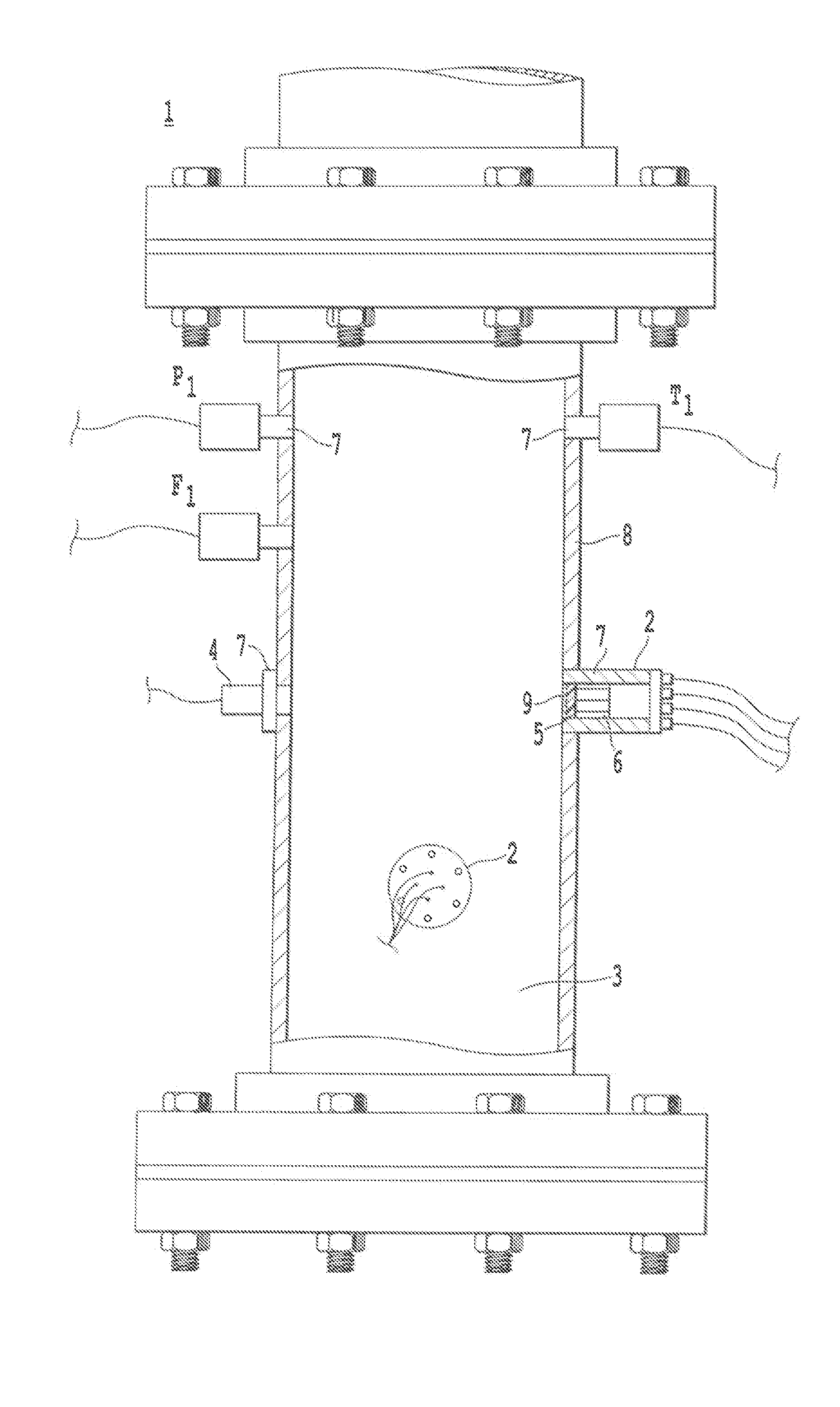
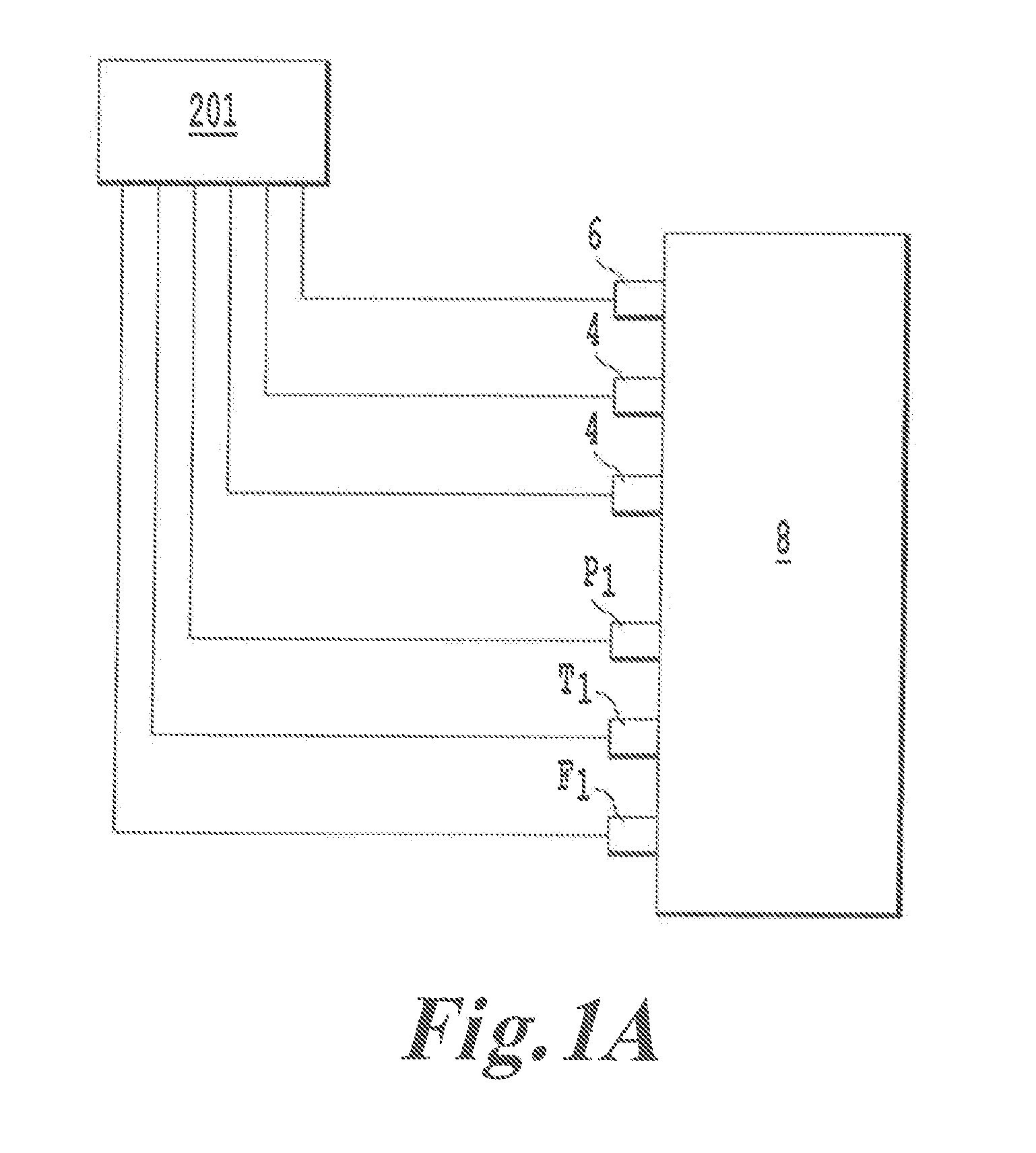
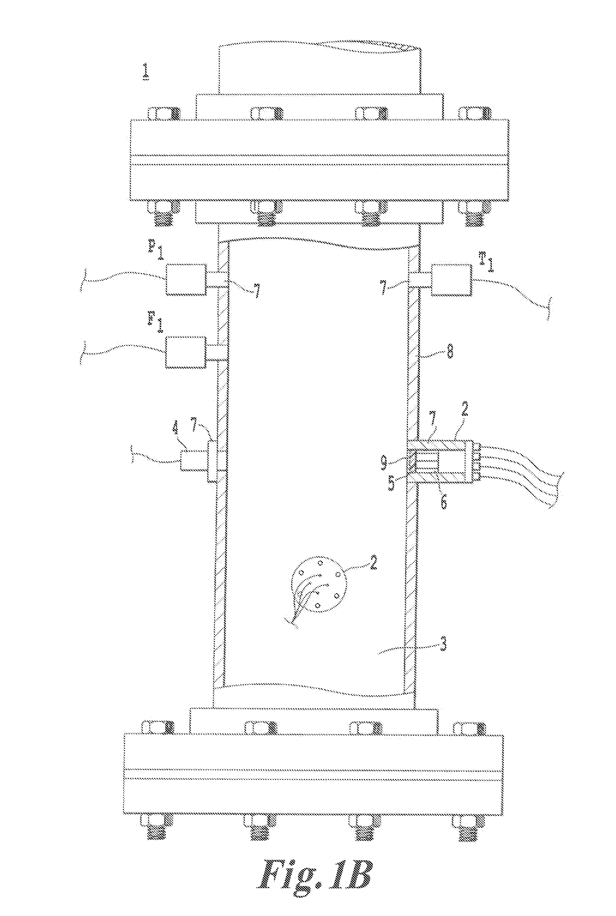
[0036]FIG. 1A is a block diagram showing the functional relationship between a computer system 201 controlling and monitoring an Ultrasound Phase Fraction Detector 1 (UPFD 1) and the components within the UPFD 1. As shown in FIG. 1A, the computer system is connected to a sensor array 6, transducer(s) 4, pressure sensor P1, temperature sensor T1, and flow meter F1 (optional), all of which are connected to the main body 8 or configured to sense information from a main body 8. The main body 8 receives a multiphase fluid, and the computer system 201 receives information sent by the sensor array 6, pressure sensor P1, temperature sensor T1, and flow meter F1 (optional) relating to the multiphase fluid. The computer system 201 then analyzes the information to determine fraction of the multiphase fluid that is water, the fraction that is gas, and the fraction that is a non-water fluid, such as diesel fuel or oil.

[0037]FIG. 1B shows one example of a UPFD 1 according to the present invention...


PUM

PropertyMeasurementUnit
temperaturesaaaaaaaaaa
temperatureaaaaaaaaaa

Abstract

An apparatus and method to determine fractions of various phases in a multiphase fluid. The apparatus includes main body including an interior configured receive a multiphase fluid and an exterior. The apparatus senses fluid pressure of multiphase fluid received in the interior and senses a fluid temperature of the multiphase fluid. The apparatus transmits an ultrasonic wave into the fluid and detects the transmitted wave to determine its velocity and attenuation. The apparatus may adjust the determined velocity and attenuation based on the temperature and pressure of the fluid to compensate for a difference between the sensed temperature and pressure and a standard temperature and pressure. The apparatus determines a gas fraction, water fraction, and a non-water fluid fraction of the multiphase fluid based on the sensed fluid pressure, the sensed fluid temperature, and the velocity and attenuation of the ultrasonic wave in the multiphase fluid.

Description

CROSS REFERENCES TO RELATED APPLICATIONS[0001]This application is a divisional of U.S. application Ser. No. 11 / 829,361, filed Jul. 27, 2007, the entire content of which is incorporated herein by reference.BACKGROUND[0002]1. Field of Invention[0003]This invention is directed to an ultrasound multiphase meter and method to detect and quantify the phase fractions and flow rates in a multiphase flow stream.[0004]2. Description of the Related Art[0005]Multiphase meters have attracted the attention of the oil production industry because of their accuracy and cost savings as opposed to analyzing discrete samples of multiphase fluid to determine fractions of oil, water, and gas. Development of accurate and compact multiphase metering devices that can be installed at well heads in remote onshore fields and unmanned offshore platforms continues to be a technological challenge. Data acquired by such devices may be used in reservoir management and production allocation inasmuch as the particula...

Claims


Application Information

Patent Timeline
Patent Type & Authority Applications(United States)
IPC IPC(8): G01F1/66
CPCG01F1/74G01N29/024G01N29/032G01N29/326G01N2291/02881G01N2291/0224G01N2291/02836G01N2291/02872G01N2291/0215
Inventor HURMUZLU, YILDIRIMANTICH, PETERDOGRU, ALIRICHER, EDMONDSMITH, BILLY
Owner MULTIPHASE FLOW INT
Learn More