Fail-operational multiple lifting-rotor aircraft

a multi-rotor aircraft and failure-operation technology, applied in the direction of rotocraft, vertical landing/take-off aircraft, vehicles, etc., can solve the problems of impending or catastrophic failure of the rotor system, its mounting or control, or the drive connection including shafting and direction-changing gearboxes, and the limited range/payload capacity of the tilt-rotor or compound aircraft, so as to prevent the failure of one rotor from interfering

Inactive Publication Date: 2010-11-04
KAREM ABE
View PDF11 Cites 34 Cited by
  • Summary
  • Abstract
  • Description
  • Claims
  • Application Information

AI Technical Summary

Benefits of technology

[0011]The current invention provides methods and apparatus in which a rotorcraft having a mechanical coupling between rotors can be disengaged and optionally reengaged, during flight, and thereby prevent a failure of one rotor from interfering with rotation of the other rotor(s). This can be accomplished using many different types of devices, including for example, dog clutches and friction clutches, and collapsible clutches.

Problems solved by technology

Any rotor system, its mounting or controls, or the drive connection including shafting and direction-changing gearboxes can suffer from impending or catastrophic failure.
The failure cause can be internal, typically a component failure, or external by the sustaining of battle damage.
The problem with that arrangement, however, is that the safety benefit in vertical flight becomes a liability in forward, wing-borne flight.
Until very recently, the range / payload capability of a tilt-rotor or compound aircraft was so limited that attention was not focused on this problem.
During hover and conversion to forward flight, all known tilt-rotor and tilt-wing aircraft cannot continue flight to a safe landing when a rotor (not an engine) fails.
However, as previously noted, these two flight regimes occupy a small and decreasing percentage of the total flight time as the utility of the aircraft improves and it becomes predominantly a transportation machine and not a lifting device.
In order to render tilt-rotor and tilt-wing aircraft acceptable for large scale transportation of passengers, it must be possible to continue wing-borne flight, in airplane mode, to a safe landing with a damaged or disabled rotor, and not to allow this single point failure to unduly compromise flight safety.

Method used


Image

  • Fail-operational multiple lifting-rotor aircraft
  • Fail-operational multiple lifting-rotor aircraft
  • Fail-operational multiple lifting-rotor aircraft

Examples


Embodiment Construction

Matrix of Flight Condition, Failure Type, and Corrective Action

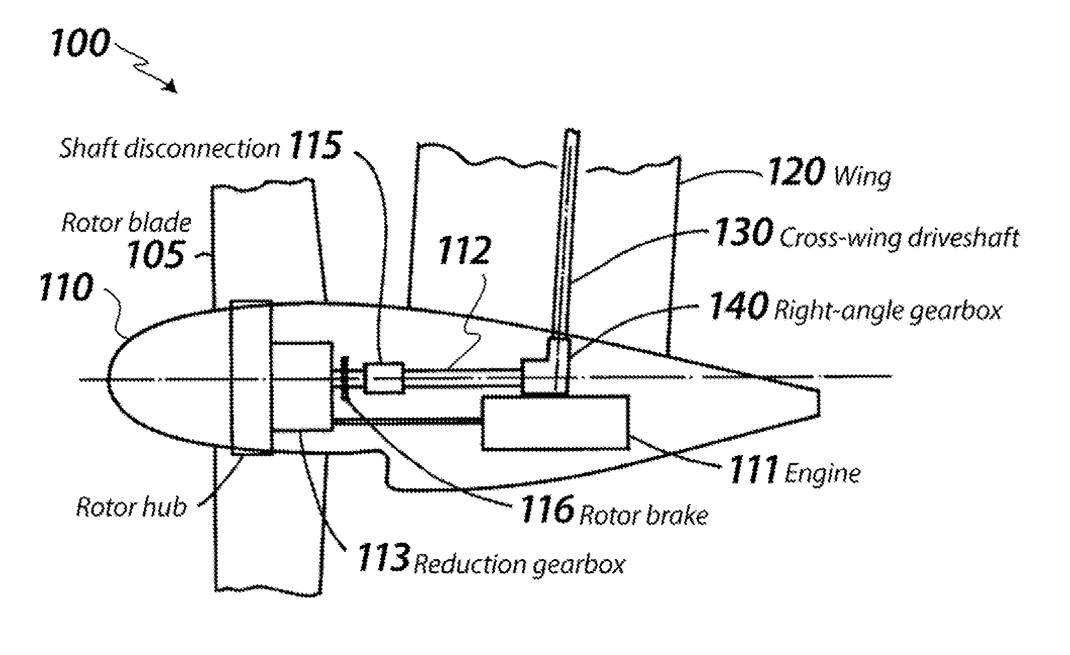
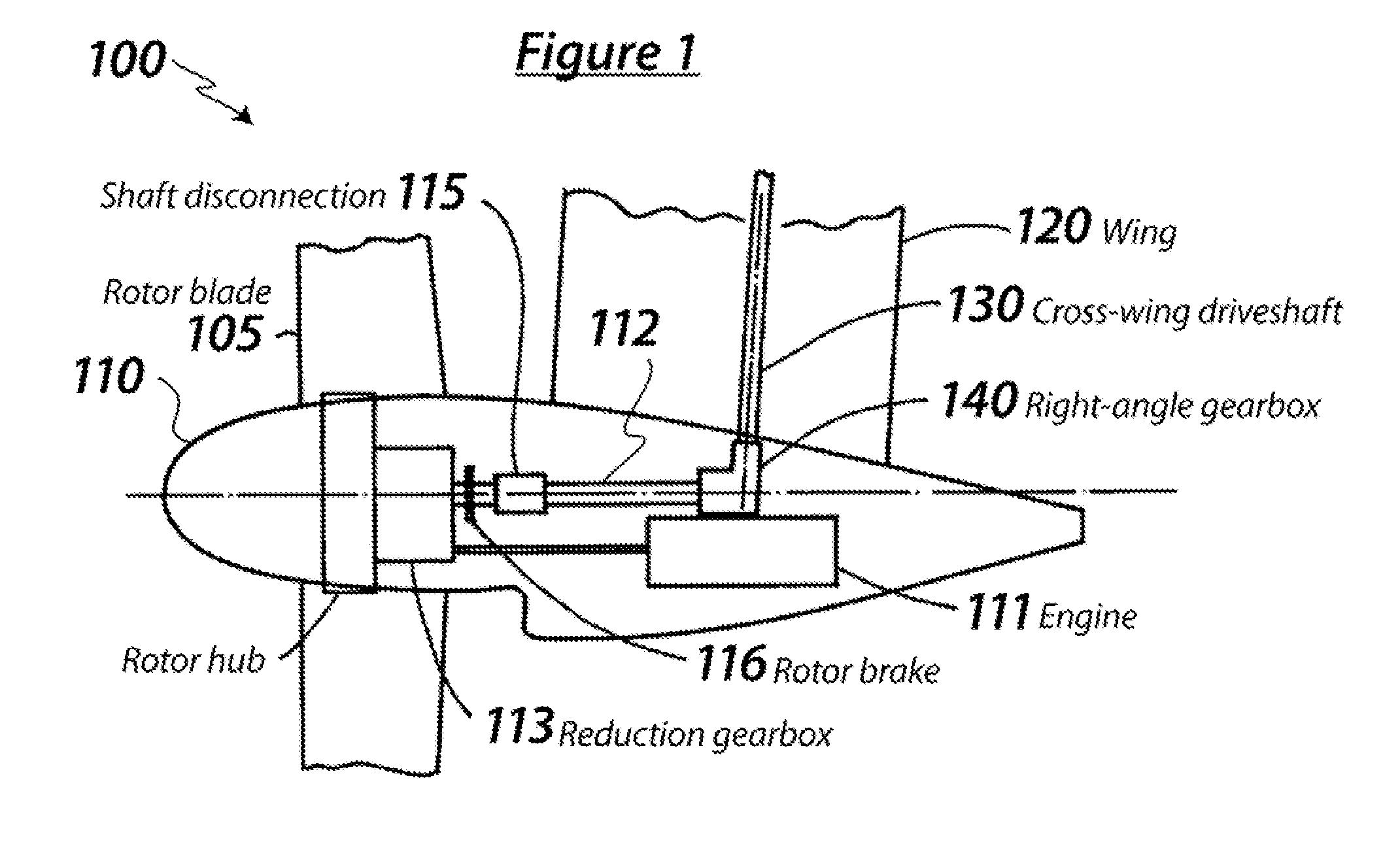
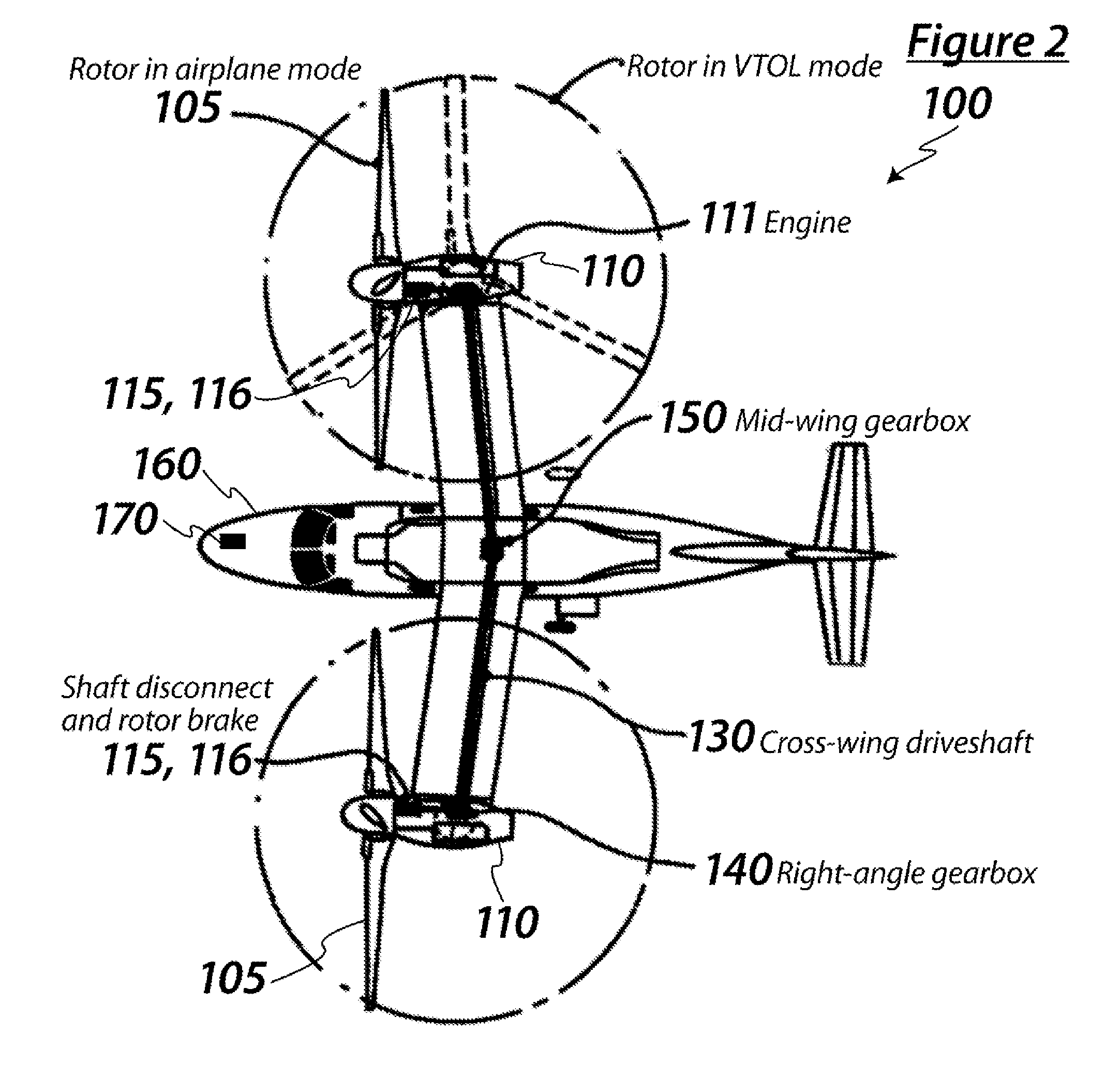
[0019]The following is a matrix of prevailing flight conditions, failure type, the shaft disconnection decision and the resulting flight safety enhancement applicable to a two-rotor tilt rotor. This is an illustrative example, and the same logic would be applied to the drive arrangements and disconnection provisions for other aircraft configurations with different drive arrangements.

FlightShaftRotor brakeregimeFailure typedisconnectionactivatedResult of actionVTOL (1)Loss of one engineNoNoPower loss but no liftimbalanceVTOL (2)Loss of one rotor,N / AN / APossibly Catastrophicrotor control or(depends on possible shaftrotor gear boxdisconnect and transition toforward flight)VTOL (3)Failed cross-wingYesNoNo impact apart fromdriveshaft or relatedlack of power plantright angleredundancygearboxesAirplaneLoss of one engineNoNoPower loss but noMode (4)thrust imbalanceAirplaneLoss of one rotor,YesYes forContinue single-Mode (5)rotor ...


PUM


Abstract

A rotorcraft having multiple rotors, and wings that provide lift in forward flight, has mechanical coupling between rotors that can be disengaged and optionally reengaged, during flight. The coupling can, which can prevent a failure of one rotor from interfering with rotation of the other rotor(s), can be accomplished using many different types of devices, including for example, dog clutches and friction clutches, and collapsible clutches. Disengagement can range from being completely under control of an operator, to partially under operator control, to completely automatic. Among many other benefits, designing, manufacturing, fitting, retrofitting or in some other manner providing an aircraft with a device that can disengage rotation of one of the rotors from that of another one of the rotors during flight can be used to improving survivability in an emergency situation.

Description

[0001]This application claims priority to U.S. Provisional Application Ser. No. 60 / 713,683 filed Sep. 2, 2005.TECHNICAL FIELD[0002]The field of the invention is multiple lifting-rotor aircraft.BACKGROUND[0003]Any rotor system, its mounting or controls, or the drive connection including shafting and direction-changing gearboxes can suffer from impending or catastrophic failure. The failure cause can be internal, typically a component failure, or external by the sustaining of battle damage. In any event, the method of monitoring the loads, vibrations, temperatures and rotational speeds will determine whether the failure is progressive or instantaneous, and whether the drive disconnection should be elective or automatic.[0004]When in forward flight, the likelihood of secondary damage to an aircraft structure due to severe vibration from, for example, the loss of a rotor blade must be minimized. Aircraft with multiple lifting-rotors always have a mechanical linkage between the rotors to...

Claims


Application Information

Patent Timeline
Patent Type & Authority Applications(United States)
IPC IPC(8): B64C27/22
CPCB64C27/08B64C29/0033B64C27/26
Inventor KAREM, ABE
Owner KAREM ABE
Why Eureka
Try Eureka