Cabin mounting structure for construction machinery

a technology for construction machinery and mounting structures, applied in soil shifting machines/dredgers, roofs, transportation and packaging, etc., can solve the problems of increasing driver fatigue, reducing work efficiency, safety accidents, etc., and achieve the effect of efficiently isolating front and rear directional vibrations without damaging the operational safety of drivers

Active Publication Date: 2010-11-04
DOOSAN INFRACORE CO LTD
View PDF41 Cites 18 Cited by
  • Summary
  • Abstract
  • Description
  • Claims
  • Application Information

AI Technical Summary

Benefits of technology

[0020]Therefore, example embodiments of the disclosure can efficiently damp both front and rear directional vibration and up and down directional vibration transferred from the vehicle body through the up and down directional vibration damping unit and the front and rear directional vibration damping unit.
[0021]Further, front and rear directional vibration is not transferred to the seat inside the cabin so that the present invention can efficiently isolate front and rear directional vibration without damaging the operational safety of the driver.
[0022]Furthermore, according to a disclosed embodiment of the present invention, the cabin is installed on the vehicle body capable of being relatively movable in a front and rear direction so that front and rear directional vibration can be more efficiently damped by the front and rear directional vibration damping unit.

Problems solved by technology

In this respect, vibration continuously transferred to a driver through the vehicle body during driving the construction machinery increases driver's fatigue so as to decrease work efficiency and cause safety accidents.
It has been reported that vibration of the cabin is harmful to physical health of the driver so that vibration of the cabin has been more strictly regulated.
However, during the process of damping front and rear directional vibration by the vibration isolator 6, only the seat of the driver is moved in a front and rear direction without moving various operational apparatuses fixed on the cabin body, so that a body of the driver sitting on the seat moves in a front and rear direction with respect to the operational apparatuses, thereby deteriorating safety of operating the vehicle.

Method used


Image

  • Cabin mounting structure for construction machinery
  • Cabin mounting structure for construction machinery
  • Cabin mounting structure for construction machinery

Examples


Embodiment Construction

[0031]Hereinafter, an embodiment of the present invention will be described with reference to the accompanying drawings in detail.

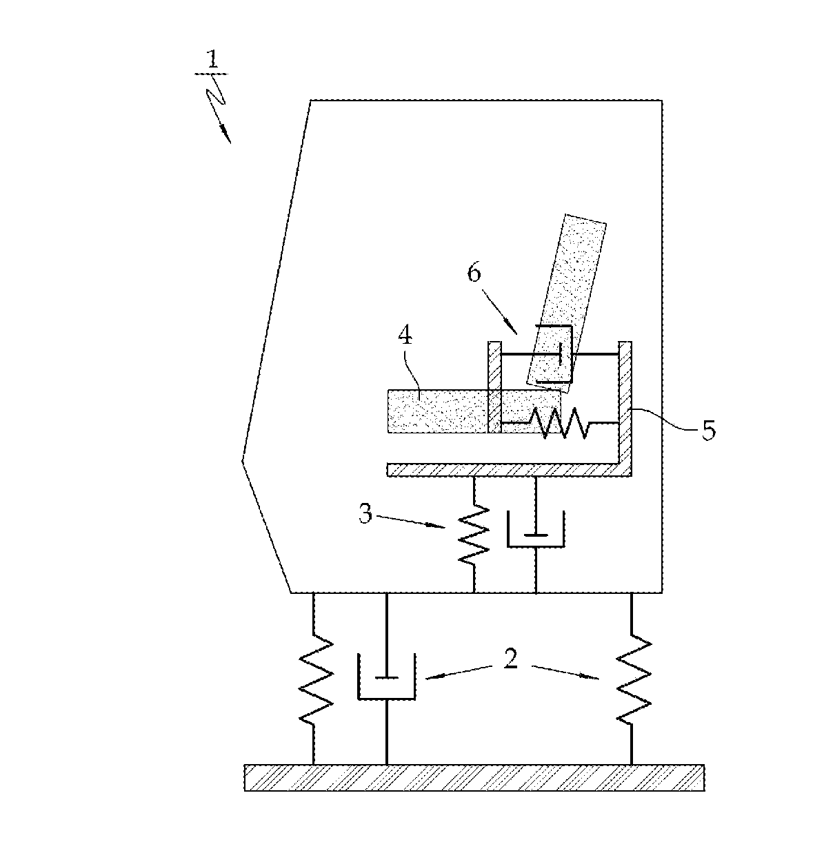
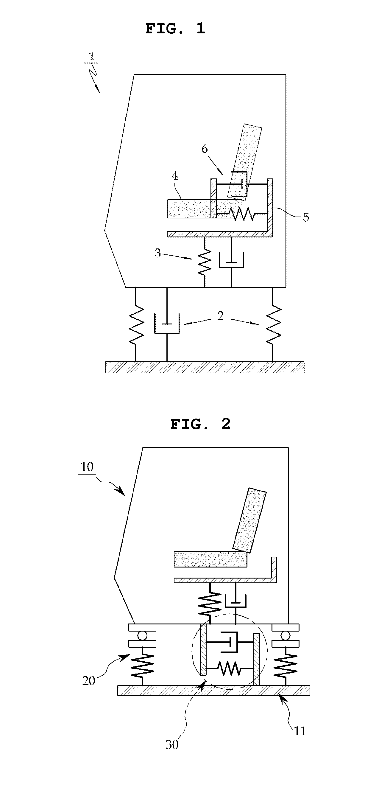
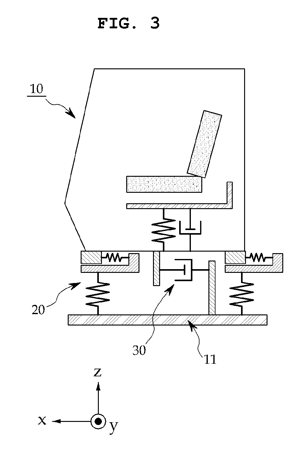
[0032]FIG. 2 is a conceptual diagram for efficiently damping vibration transferred from a vehicle body to a cabin 10 of the construction machinery according to an embodiment of the present invention, and FIG. 3 is a conceptual diagram for illustrating a vibration damping structure for the construction machinery of FIG. 2 from another aspect according to an exemplary embodiment of the present invention.

[0033]As illustrated in FIGS. 2, 4, and 5, a cabin mounting structure according to an embodiment of the present invention is for damping both up and down directional vibration and front and rear directional vibration of the whole cabin 10 and includes an up and down directional vibration damping unit 20 and a front and rear directional vibration damping unit 30 mounted between the cabin 10 and a vehicle body 11.

[0034]As illustrated in FIG. 6, the up and down...


PUM


Abstract

A cabin mounting structure is applied to construction machinery in which a cabin for riding a driver is mounted on a vehicle body, the cabin mounting structure including: an up and down directional vibration damping unit for damping up and down directional vibration of the cabin, the up and down directional vibration damping unit being mounted between the cabin and the vehicle body; and a front and rear directional vibration damping unit for damping front and rear directional vibration of the cabin, the front and rear directional vibration damping unit 3 being mounted between the cabin and the vehicle body, wherein the cabin is connected to the vehicle body to be relatively movable in a front and rear direction.

Description

CROSS-REFERENCE TO RELATED APPLICATIONS[0001]This Application is a Section 371 National Stage Application of International Application No. PCT / KR2008 / 007651, filed Dec. 24, 2008 and published as WO 2009 / 084856 on Jul. 9, 2009 in English.FIELD OF THE DISCLOSURE[0002]The present disclosure relates to construction machinery, such as an excavator or a wheel loader, and more particularly to a cabin mounting structure for construction machinery which can not only efficiently damp vibration transferred to a driver in a cabin, but also improve work efficiency.BACKGROUND OF THE DISCLOSURE[0003]A cabin, a driving compartment, is mounted on a vehicle body of construction machinery, such as an excavator or a wheel loader. In this respect, vibration continuously transferred to a driver through the vehicle body during driving the construction machinery increases driver's fatigue so as to decrease work efficiency and cause safety accidents. It has been reported that vibration of the cabin is harmf...

Claims


Application Information

Patent Timeline
Patent Type & Authority Applications(United States)
IPC IPC(8): B62D24/04
CPCE02F9/166B62D33/0604E02F9/08E02F9/16
Inventor JANG, HAN KEE
Owner DOOSAN INFRACORE CO LTD
Why Eureka
Try Eureka