Polarized white light emitting diode

a light-emitting diode, polarized technology, applied in the direction of spectral modifiers, semiconductor devices, lighting and heating apparatus, etc., can solve the problems of high color temperature, non-uniform illuminated light generation, and the inability to attract yellow phosphor grains

Inactive Publication Date: 2010-11-04
NAT TAIWAN UNIV OF SCI & TECH
View PDF7 Cites 73 Cited by
  • Summary
  • Abstract
  • Description
  • Claims
  • Application Information

AI Technical Summary

Benefits of technology

[0012]An exemplary polarized white light emitting diode comprises a substrate with a circuit formed thereon. An ultraviolet light emitting diode (UV LED) chip is disposed over the substrate and electrically connected with the circuit, wherein the UV LED chip has an emission surface for emitting ultraviolet (UV) light. A phosphor layer is coated around the UV LED chip, wherein the phosphor layer is formed by blending multi-color phosphor grains with a transparent optical resin, and the multi-color phosphor grains in the transparent optical resin are excited by the UV light from the UV LED chip to thereby emit white light. An omni-directional reflector is disposed over the phosphor layer and opposite to the emission surface of the UV LED chip. A medium is disposed between the omni-directional reflector an

Problems solved by technology

However, the white LED using the blue LED to excite the yellow phosphor grains suffers from some drawbacks.
First, high color temperatures and non-uniform illuminated light are generated due to the blue light.
Second, the wavelength of blue light shifts as temperature increases, resulting in color shift of the white light emission.
Third, insufficient color rendering occurs due to lack of the intensity of red light.
Fourth, the emitted white light produced is non-polarized white light, which r

Method used


Image

  • Polarized white light emitting diode
  • Polarized white light emitting diode
  • Polarized white light emitting diode

Examples


embodiment

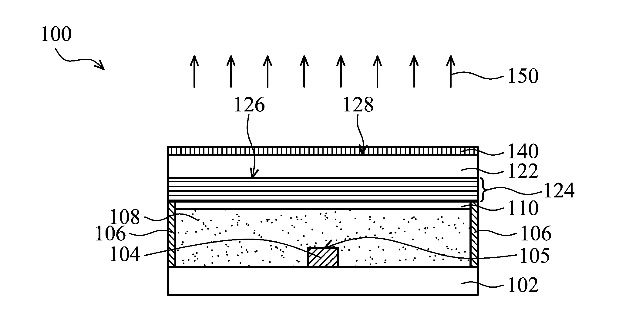
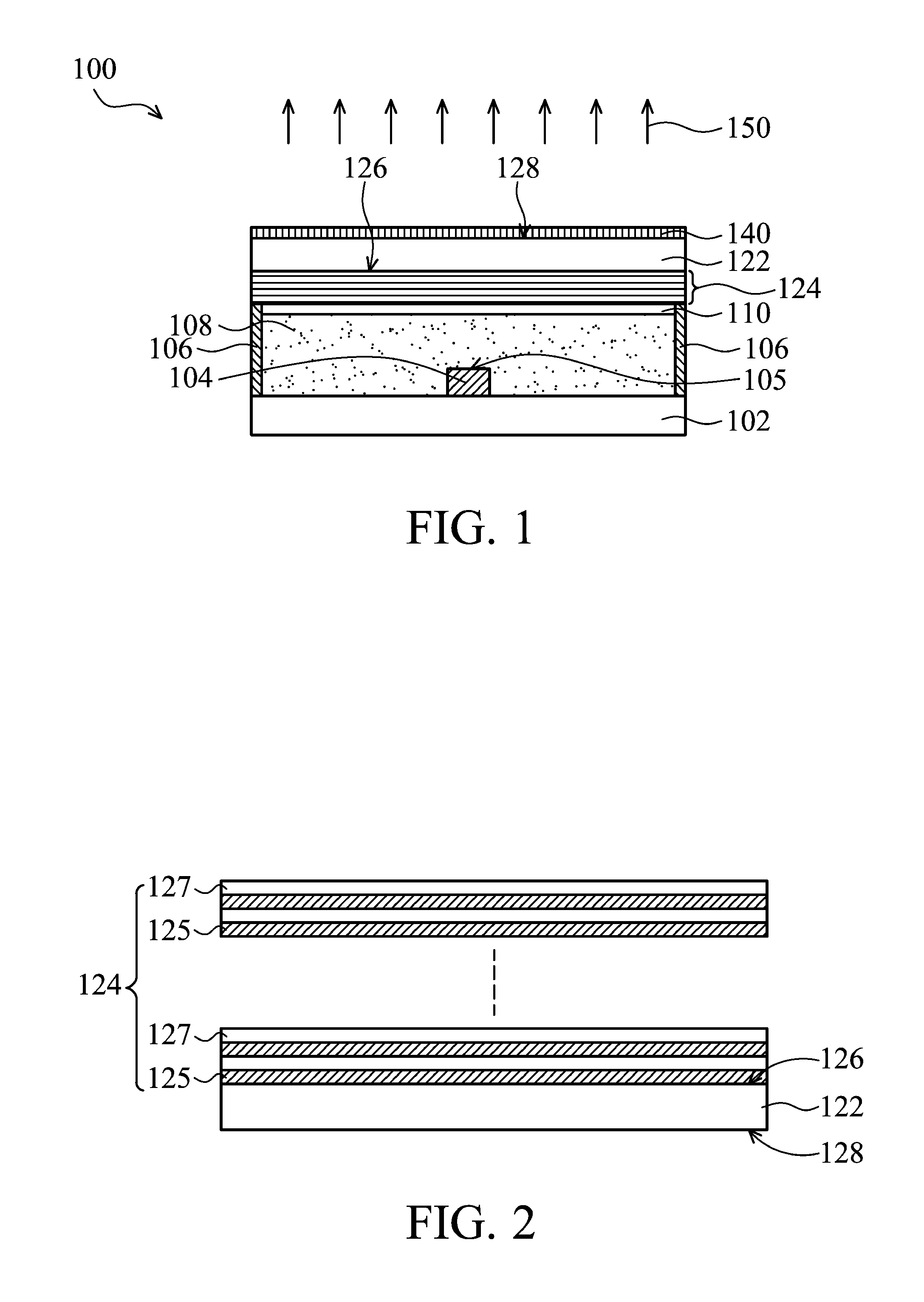
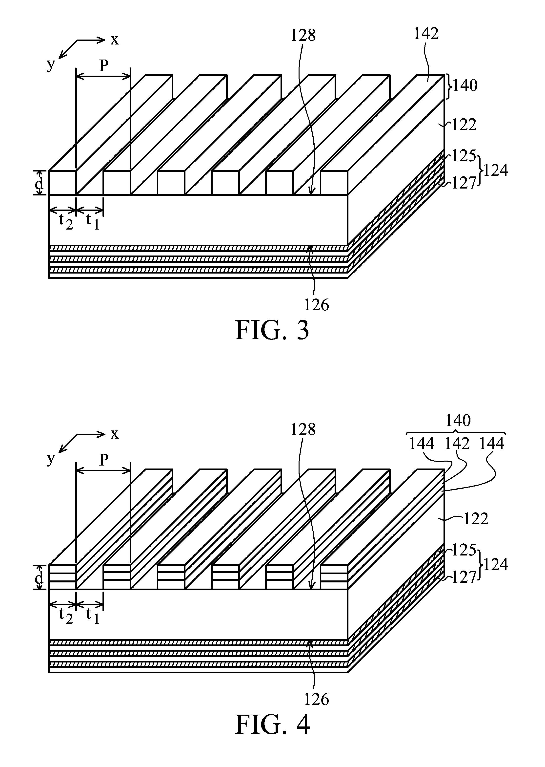
[0044]The polarized white LED 100 illustrated in FIG. 1 is provided, including a phosphor layer incorporating phosphor grains of blue, yellow and red colors, a UV LED chip, an omni-directional reflector including twenty layers of alternate deposition of high refractive index layers (made of Nb2O5 or TiO2) and low refractive index layers (made of SiO2), and a metal-containing polarization layer of a sub-wavelength aluminum metal grating having a period of about 100 nm. As shown in FIG. 7, an average reflectance (in a wavelength range of about 450-750 nm) simulation result of the sub-wavelength aluminum metal grating has a duty cycle of 50% and an incident angle of about 0-70 degrees is illustrated. Against all light incident angles, the metal-containing polarization layer shows a high average reflectance of over 90% to the TE light components and a low average reflectance of not more than 10% to the TM light components. A large reflectance difference exists between TM light component...


PUM


Abstract

A polarized white light emitting diode is provided, including a substrate with an ultraviolet light emitting diode (UV LED) chip disposed thereover for emitting ultraviolet (UV) light, a phosphor layer coated around the UV LED chip to be excited by the UV light from the UV LED chip to thereby emit white light, an omni-directional reflector disposed over the phosphor layer, a medium layer disposed between the omni-directional reflector and the phosphor layer, wherein the omni-directional reflector allows the UV light from the UV LED chip to be multiply and omni-directionally reflected in between the phosphor layer and the medium layer, a transparent substrate disposed over the omni-directional reflector, and a metal-containing polarization layer disposed over the transparent substrate for polarizing the white light emitted from the phosphor layer to thereby emit a polarized white light

Description

CROSS REFERENCE TO RELATED APPLICATIONS[0001]This Application claims priority of Taiwan Patent Application No. 98114609, filed on May 1, 2009, the entirety of which is incorporated by reference herein.BACKGROUND OF THE INVENTION[0002]1. Field of the Invention[0003]The present invention relates to light emitting diodes (LEDs), and in particular relates to a polarized white light emitting diode capable of emitting polarized white light.[0004]2. Description of the Related Art[0005]White light-emitting diodes (LEDs) are point light sources that are packaged as a matrix LED for illumination. White light is produced by combining at least two chromatic lights with various wavelengths, such as blue and yellow light or blue, green and red light.[0006]Because light sources emitting light in spectrum ranges closer to sunlight are desirable, white LEDs with specific spectrums, color renderings and correlated color temperatures (CCTs) similar to sunlight have been developed. The color rendering ...

Claims


Application Information

Patent Timeline
IPC IPC(8): F21V9/14
CPCH01L33/44H01L33/46H01L33/50H01L2933/0083H01L2224/48247H01L2224/48091H01L2924/00014
Inventor SU, JUNG-CHIEHHSU, CHE-WEI
Owner NAT TAIWAN UNIV OF SCI & TECH
Why Eureka
Try Eureka