Electroacoustic transducer

a transducer and electroacoustic technology, applied in the direction of transducer details, electrical transducers, plane diaphragms, etc., to achieve the effect of increasing the magnetic flux density for effective action, and reducing the volume of magnets used

Active Publication Date: 2010-11-04
HANADA AKITO
View PDF3 Cites 32 Cited by
  • Summary
  • Abstract
  • Description
  • Claims
  • Application Information

AI Technical Summary

Benefits of technology

This patent describes an improved design for an electroacoustic transducer (a type of speakers). By adding a new magnet configuration and arranging certain parts of the transducer's construction, this design can reduce the amount of magnet needed while still maintaining efficient use of its power. Additionally, the design allows for better control over the distribution of magnetic field strength, resulting in higher levels of audio output from the transducer. Overall, these technical improvements make the electroacoustic transducer more compact, cost-effective, and easier to produce than previous designs.

Problems solved by technology

The technical problem addressed in this patent text relates to improving the performance of an electroacoustic transducer known as a Gambus type or Planar Coil Type speakers. These speakers have limitations in terms of their overall size and the consistence of the driving force across the whole face of the audio device due to factors such as changes in magnetic flux density and the orientation of the electric currents. Prior solutions also had difficulty in expanding the usable space without sacrificing sound quality.

Method used


Image

  • Electroacoustic transducer
  • Electroacoustic transducer
  • Electroacoustic transducer

Examples


embodiment 1

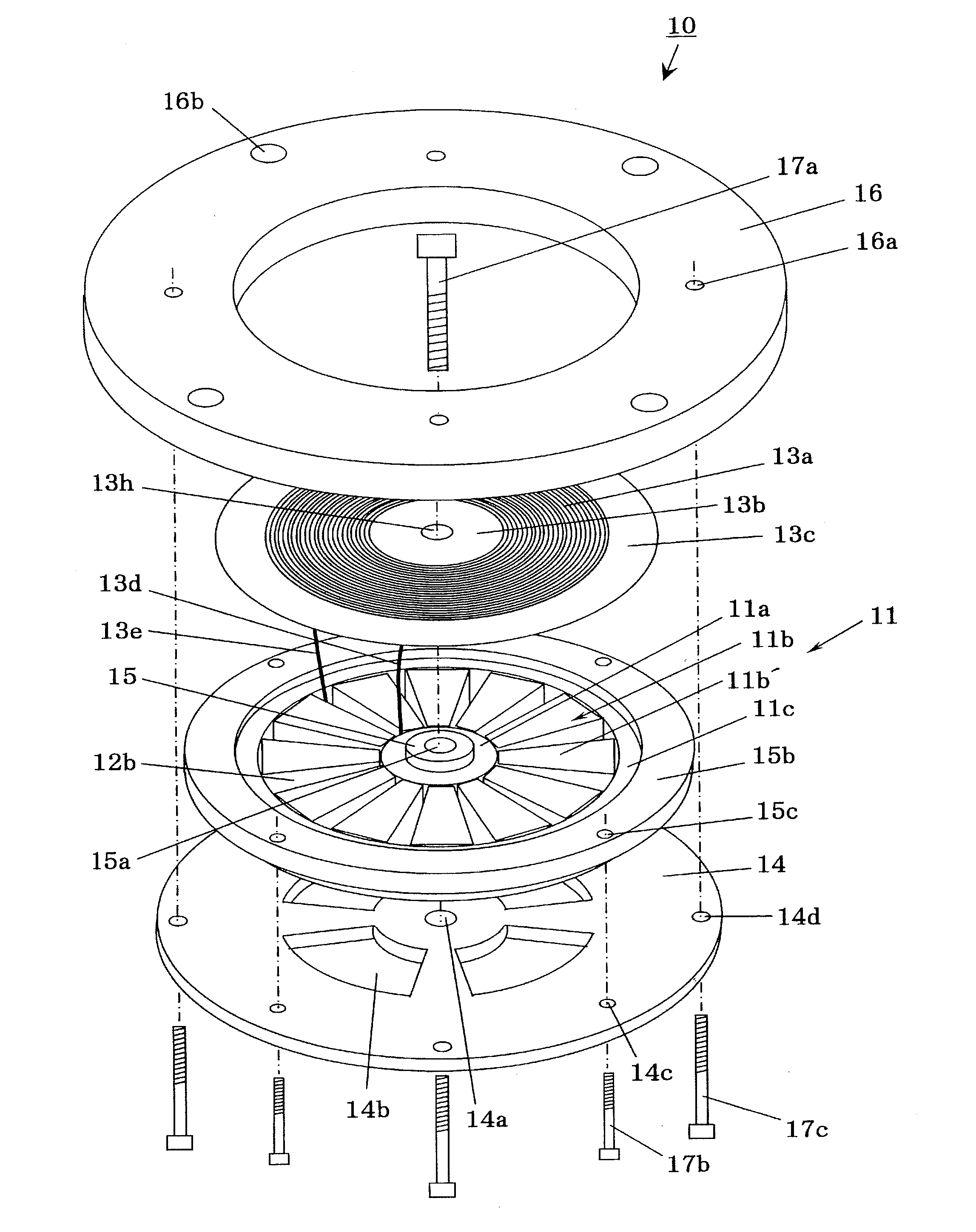
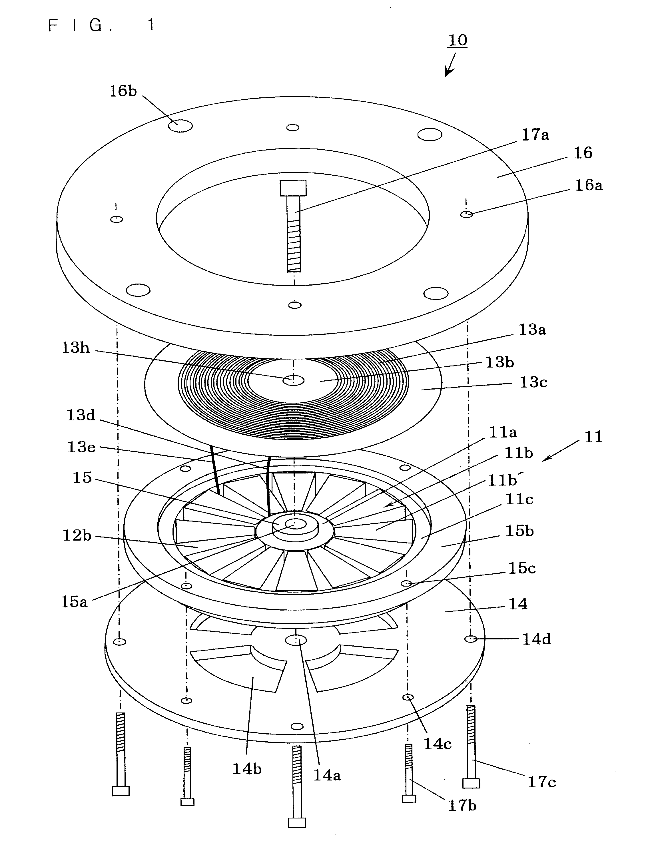
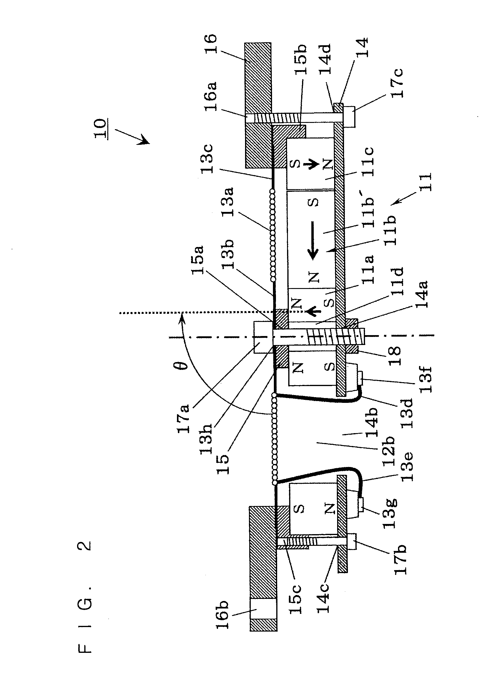
[0153]FIG. 1 is a disassembled perspective view showing an electroacoustic transducer according to Embodiment 1. FIG. 2 is a schematically sectional end view showing the major parts of the electroacoustic transducer according to Embodiment 1.

[0154]In FIG. 1 and FIG. 2, reference numeral 10 denotes an electroacoustic transducer according to Embodiment 1, 11 denotes a magnet plate of the electroacoustic transducer 10 the entirety of which is composed to be roughly disk-shaped, 11a denotes a center area magnet using a ring-shaped neodymium magnet at partial areas of the magnet plate 11, 11b denotes a base area magnet composed of twelve trapezoidal small magnets 11b′ using neodymium magnet at partial areas of the magnet plate 11, 11c denotes an outer circumference area magnet using a ring-shaped neodymium magnet at partial areas of the magnet plate 11, and 11d denotes an insertion hole of a bolt 17a secured at the middle of the center area magnet 11a. Reference numeral 12b denotes twelv...

embodiment 2

[0185]FIG. 3 is a schematically sectional end view showing the major parts of an electroacoustic transducer according to Embodiment 2.

[0186]In FIG. 3, reference numeral 20 denotes an electroacoustic transducer according to Embodiment 2, 21 denotes a magnet plate of the electroacoustic transducer 20 the entirety of which is composed to be disk-shaped, 21a denotes a center area magnet using a ring-shaped neodymium magnet at partial areas of the magnet plate 21, 21b denotes a base area magnet composed of a plurality of trapezoidal small magnets 21b′ using a neodymium magnet at partial areas of the magnet plate 21, 21d denotes a front center area magnet having a semispherical forward portion, which is installed at the front center part of an acoustic diaphragm 23a, is formed to be ring-shaped, and uses a neodymium magnet, and 21e denotes a front outer circumference area magnet that is installed at the front outer circumference portion of the acoustic diaphragm 23a and uses a ring-shaped...

embodiment 3

[0215]FIG. 4 is a schematically sectional end view showing the major parts of an electroacoustic transducer according to Embodiment 3.

[0216]In FIG. 4, reference numeral 30 denotes a composite-type electroacoustic transducer according to Embodiment 3, which is composed by concentrically disposing a high-range electroacoustic transducer 40 and a low-range electroacoustic transducer 50 each of which is independently formed. Reference numeral 41 denotes a magnet plate of a high-range electroacoustic transducer 40, the entirety of which is composed to be disk-shaped, 41a denotes a high-range center area magnet using a ring-shaped neodymium magnet at a partial area of the high-range magnet plate 41, and 41b denotes a high-range base area magnet composed of a plurality of trapezoidal small magnets 41b′ each using a neodymium magnet at a partial area of the high-range magnet plate 41. Reference numeral 42b denotes a high-range sound passage port formed between the trapezoidal small magnets ...


PUM


Abstract

The invention provides an electroacoustic transducer capable of efficiently carrying out conversion from electric signals to sound or from sound to electric signals at low distortion, which requires no special shape nor processing as a magnet, requires no minute setting of the magnetization direction, and sets a distribution of higher magnetic flux densities for effective action with respect to an electric conductor of an acoustic diaphragm than in a magnet plate magnetized in the radius direction although the production process thereof is remarkably simple as in a magnet plate magnetized in the radius direction.
The electroacoustic transducer is provided with at least any one of the center area magnet magnetized so that a component parallel to the center axis of the acoustic diaphragm is turned into the forward direction of the acoustic diaphragm at the position that becomes the center side of the base area magnet and the outer circumference area magnet magnetized so that a component parallel to the center axis of the acoustic diaphragm is turned into the backward direction of the acoustic diaphragm at the position that becomes the outer circumference side of the base area magnet, in addition to a base area magnet magnetized so that a component parallel to the vibration plane of the acoustic diaphragm is turned into the radius direction toward the center of the acoustic diaphragm with respect to the magnetization direction of respective partial areas of a magnet plate.

Description


Claims


Application Information

Patent Timeline
Owner HANADA AKITO
Why Eureka
Try Eureka