
Near real-time viewer for pet-guided tissue interventions

Inactive Publication Date: 2010-11-04
COMPANIA MEXICANA DE RADIOLOGIA CGR S A DE
View PDF10 Cites 6 Cited by
  • Summary
  • Abstract
  • Description
  • Claims
  • Application Information

AI Technical Summary

Benefits of technology

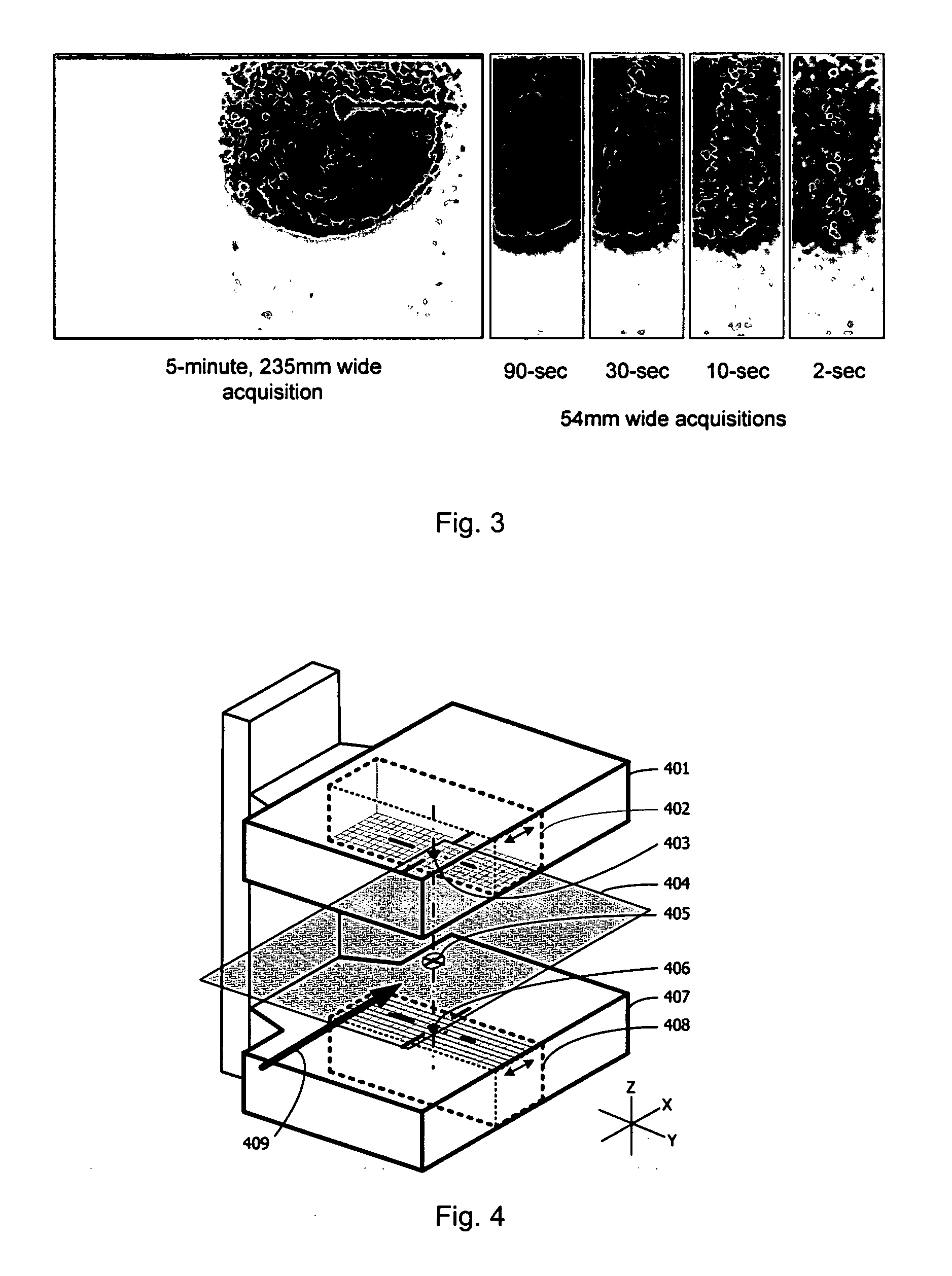
[0027]In another aspect, the invention provides a system for localizing a positron-emitting source during an intervention relating to a body part. The system comprises a positron emission tomography (PET) scanner having at least two detectors and a display monitor. The PET scanner is configured to enable a user to acquire a diagnostic image of the body part and to use the acquired image to determine a location of a lesion within the body part; and to further enable the user to position the at least two detectors such that the determined lesion location is within a field of view of each of the at least two detectors, and to obtain a persistence image of the lesion within a predetermined focal plane using the positioned detectors. The displ

Problems solved by technology

Cancer is a major threat and concern to the population.
However, neither of these modalities allows the ability to track the progress of the intervention with respect to the changes in cellular functional which may be associated with neoplasia and is therefore important for interventional guidance.
A limitation for performing interventions using nuclear-emission localization such as FDG-PET is the inability to simultaneously image a region of suspicious tissue together with the interventional device for completely describing their relative positions, because the devices do not produce a signal that is detectable by nuclear-emission imaging techniques.

Method used


Image

  • Near real-time viewer for pet-guided tissue interventions
  • Near real-time viewer for pet-guided tissue interventions
  • Near real-time viewer for pet-guided tissue interventions

Examples


Embodiment Construction

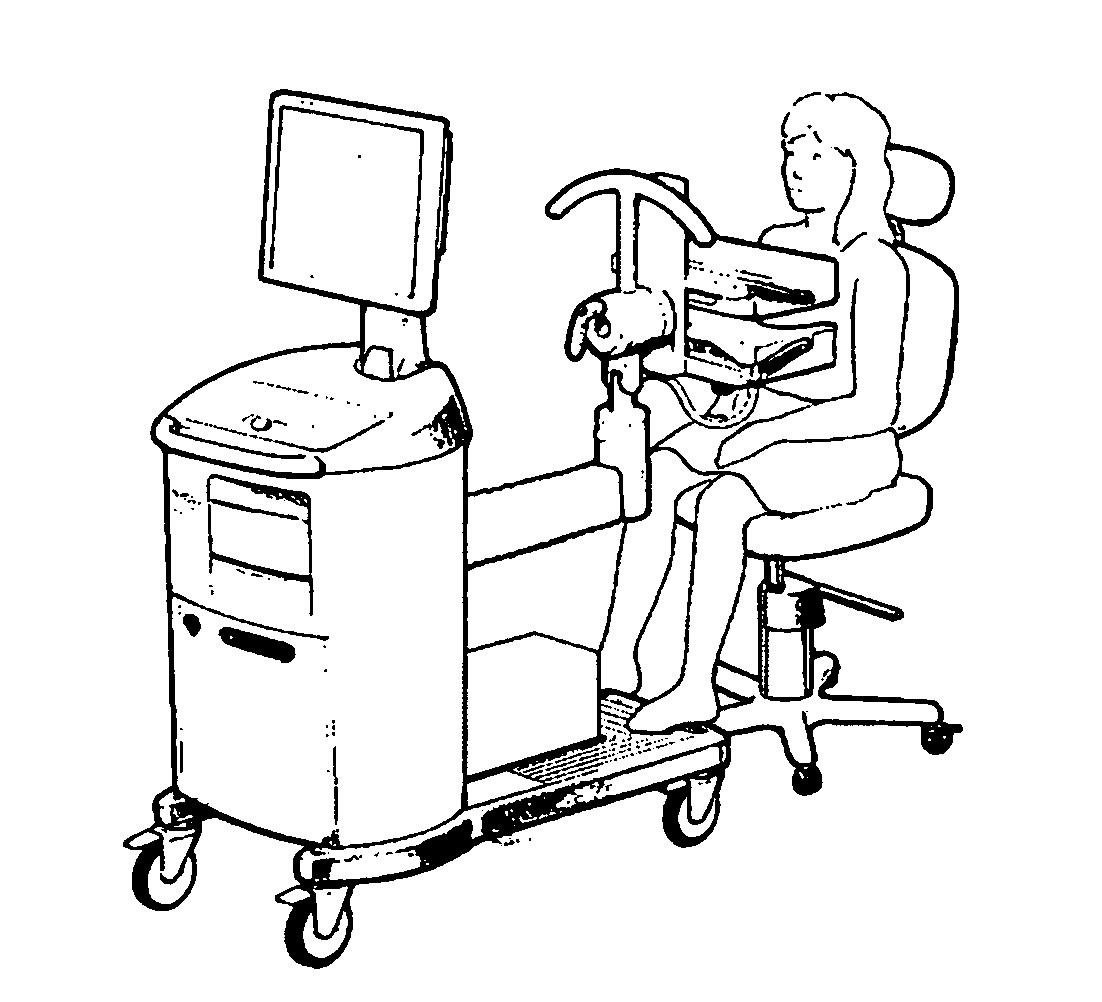
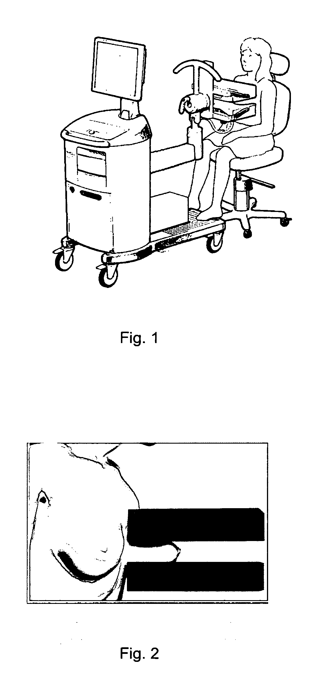
[0037]A preferred embodiment of the invention includes the subject method used in conjunction with a high-resolution PET scanner capable of compressing and immobilizing target tissue labeled with a positron-emitting radiopharmaceutical (e.g., FDG) for a stereotactic or manually-guided intervention. A second preferred embodiment includes the additional element of a radioactive marker affixed to the interventional device such that its position can be detected with the PET scanner. A third preferred embodiment involves the use of the method to determine the position and orientation of the interventional device relative to the lesion.

[0038]In a typical PET scan, there are very large number of different coincidence lines (also commonly referred to as lines of response, or LORs) through the three dimensional space between the opposing detector modules. A sufficient number and quality of LORs (and the associated time to acquire them) are necessary to provide good statistical data for image...


PUM


Abstract

An apparatus and a computational method are provided for localizing a positron-emitting source during an intervention using positron emission tomography (PET) imaging. The apparatus is designed to accelerate the image acquisition and reconstruction process such that the resulting image presentation can be used to quickly reposition an interventional device in relation to a lesion. By limiting the processing of data in the acquisition to a focal plane which extends through the localization target, and which is oriented to capture and display motion during the intervention, and then by displaying a persistence image which is frequently refreshed, a user can visualize movement of the positron-emitting source for optimizing the position of the interventional device. The positron-emitting source(s) can be radiolabeled tissue, a radiolabeled interventional device, a radiolabeled fiducial, or any combination thereof.

Description

CROSS REFERENCE TO RELATED APPLICATIONS[0001]The application is a continuation of U.S. patent application Ser. No. 12 / 603,203, filed Oct. 21, 2009, and claims priority benefit to Provisional U.S. Patent Application No. 61 / 107,607, filed Oct. 22, 2008, the contents of which are incorporated herein in their entirety.BACKGROUND OF THE INVENTION[0002]1. Field of the Invention[0003]The present invention relates generally to an apparatus and method for positioning interventional devices using PET imaging. More particularly, the present invention relates to a system and method for reducing the time needed to track and display the physical relationship between an interventional device and a lesion as the interventional device is being applied.[0004]2. Description of Related Art[0005]Cancer is a major threat and concern to the population. Early detection and complete treatment of suspicious or cancerous lesions has been shown to improve long-term survival. Ex-vivo imaging modalities such as ...

Claims


Application Information

Patent Timeline
IPC IPC(8): A61B6/12
CPCA61B5/055A61B6/037G06T2210/41G06T19/00
Inventor LU, XIAOHONGYARNALL, STEPHEN T.
Owner COMPANIA MEXICANA DE RADIOLOGIA CGR S A DE
Learn More