Translucent building block and a method for manufacturing the same

a technology of building blocks and transparent materials, applied in the direction of lamination, structural elements, building components, etc., can solve the problems of inability to easily conform the properties of translucent materials to complex architectural requirements, the requirement of correct fitting of discrete elements, and the limited number and size of transparent members, etc., to achieve the effect of sufficient rigidity

Active Publication Date: 2010-11-11
LOSONCZI ARON
View PDF35 Cites 13 Cited by
  • Summary
  • Abstract
  • Description
  • Claims
  • Application Information

AI Technical Summary

Benefits of technology

[0012]Therefore, as claimed in claim 1, for the building block having translucent properties between said first boundary surface and said second boundary surface spaced from the first boundary surface, the translucent properties are provided by discrete translucent members extending between said boundary surfaces and being spaced form one another. Said building block is formed by a cast material filling the spaces between the translucent members, said translucent members have sufficient rigidity to preserve their positions under the effect of forces applied by the casting of said cast material. Said translucent members are interconnected by means of connection elements to constitute an integral mechanical structure. According to the invention, the translucent elements are arranged in at least one discrete gr

Problems solved by technology

The number and the sizes of the transparent members are limited by economical, static, heat insulating and mechanical requirements relating to the closure members, walls and roofs, as above properties of the translucent materials cannot easily be conformed to the complex architectural requirements.
However, its disadvantage that it requires correct fitting of discrete elements at predetermined locations during building of the wall structure.
Such projecting strips encumber the bricklaying job and the load bearing property of a wall consisting of such elements is limited to a great extent because of the risk of slipping at contact areas between the glass and binding material.
Disadvantage of this method is that it is very labour-intensive and the application of glass fibres involves extremely high costs.
Shortcoming of both solutions relates to their costs incurred by the application of glass fibres.
A further common disadvantage of the solutions above that the translucent members are positioned randomly or the grouping of members is labour intensive or impossible.
Disadvantage of this solution is that the adequate forming of the retainer sheet having no role in the light guidance requires further dead-works and costs, and remaining on the building member it restrains application thereof, in the case of removing it forms wastes, moreover, in the case of production of thicker building blocks or applying slimmer and/or less rigid translucent members

Method used


Image

  • Translucent building block and a method for manufacturing the same
  • Translucent building block and a method for manufacturing the same
  • Translucent building block and a method for manufacturing the same

Examples


Embodiment Construction

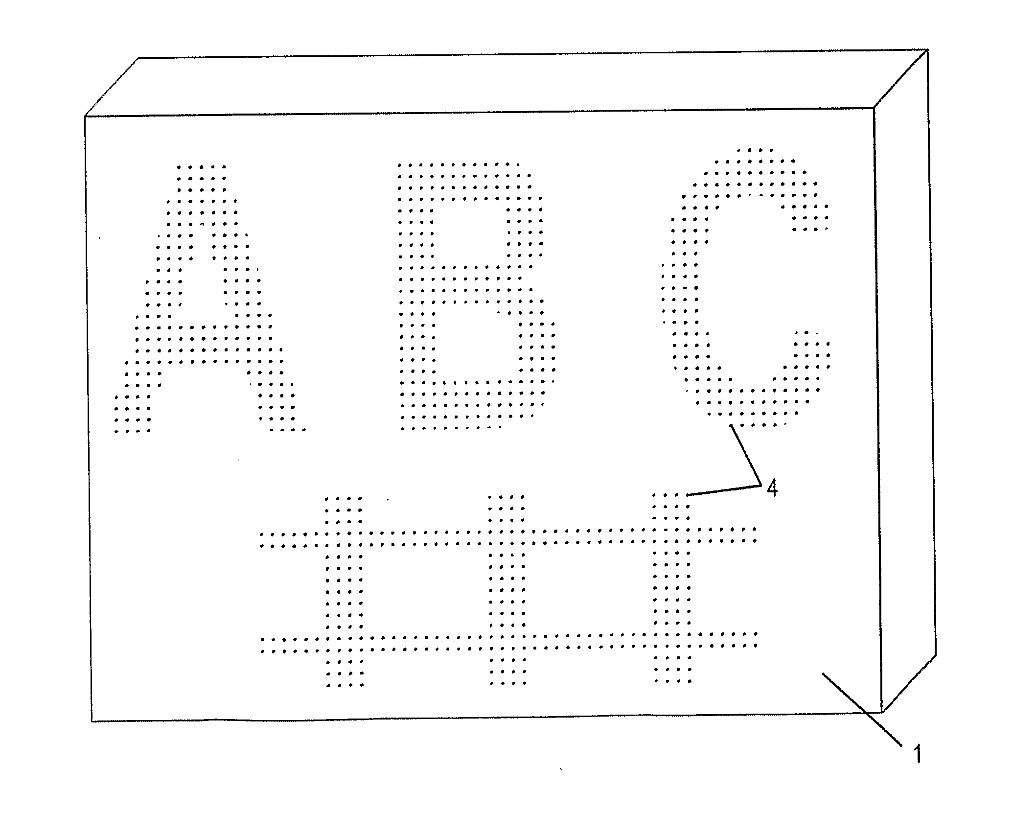
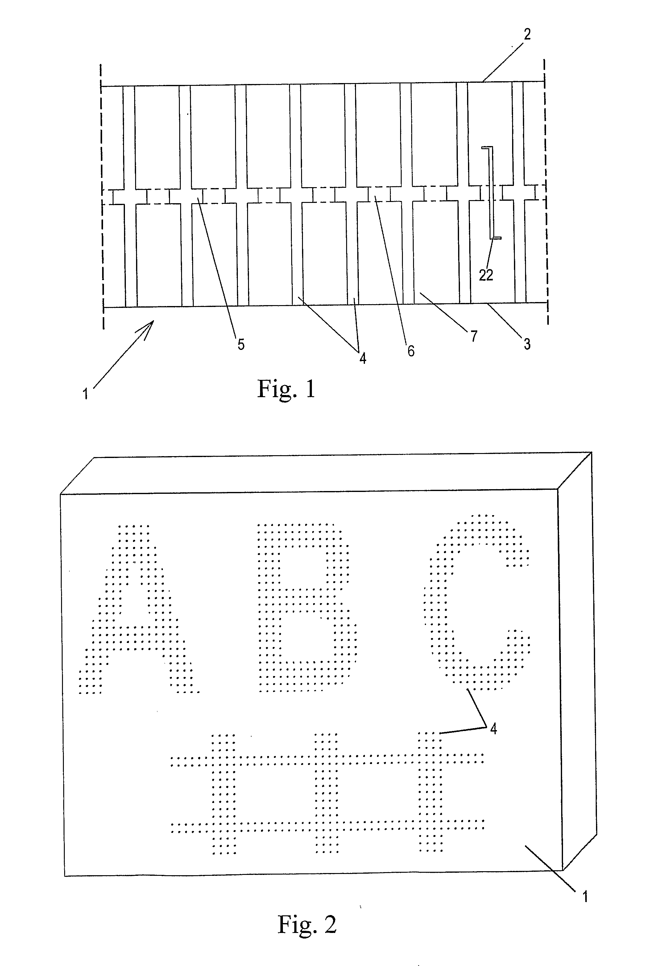
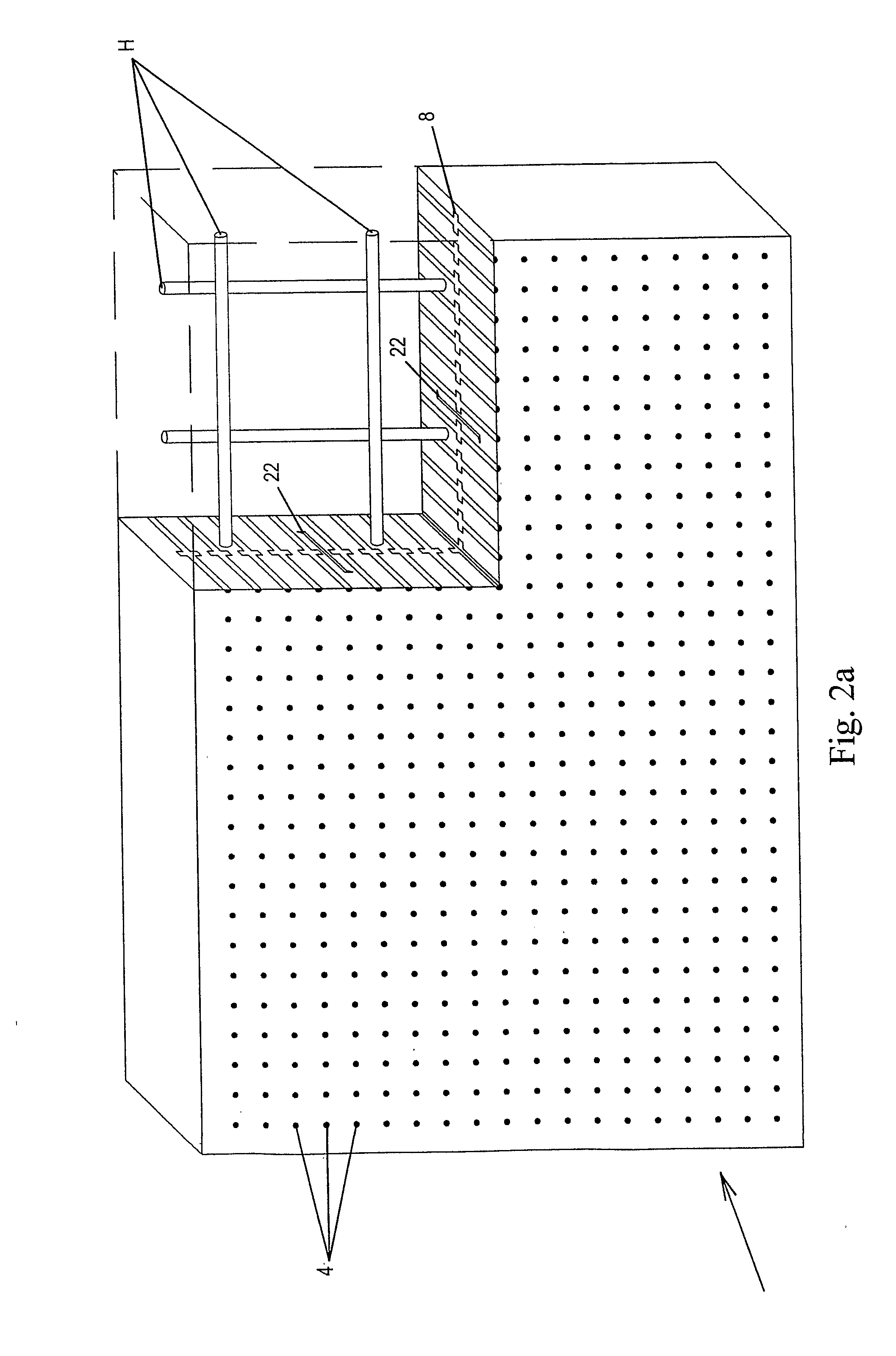
[0044]FIG. 1. is a cross section of a preferred embodiment of the translucent building block according to the invention. The translucent building block 1 shown has at least two, namely a first and a second bounding surfaces 3. In order to have translucent property the building block 1 has to have at least one, a plurality in the drawing, relatively rigid translucent member 4 having surfaces—preferably but non exclusively—fairly polished, and arranged at least partly between the first and a second bounding surfaces 3, so that the translucent member 4 is surrounded by cast material 7. In this description the term “relatively rigid” means a mechanical property allowing the translucent member to bear forces acting in the course of the flow of cast material 7 during moulding, without permanent deformation. In a preferred embodiment not shown in the drawing the translucent members 4 may protrude beyond the bounding surfaces 2, 3, that is the translucent members 4 may poke out of the build...


PUM

PropertyMeasurementUnit
Lengthaaaaaaaaaa
Strengthaaaaaaaaaa
Translucencyaaaaaaaaaa

Abstract

The invention relates to a translucent building block (1) having at least two, a first and a second bounding surfaces (2, 3), between which there is at least a part of a translucent member (4) and cast material surrounding said member (4) connected to an retainer structure (5), whereas the latter is arranged between said surfaces (2, 3). The invention also relates to a an insert (8) for producing a translucent building block (1) having an retainer structure (5) and at least one translucent member (4) arranged on said auxiliary retainer (5), and the translucent member (4) has at least one section (9, 10) projecting from said retainer structure (5), and said insert is provided with an opening formed on said retainer structure (5) and/or with a fixing member (19, 20, 21). The invention also discloses a method for producing a translucent building block (1).

Description

[0001]This invention relates to a building block with translucent properties between a first boundary surface and a second boundary surface spaced from the first boundary surface, the translucent properties are provided by discrete translucent members extending between the boundary surfaces and they are spaced form one another, the building block is formed by a cast material filling the spaces between the translucent members, the translucent members have sufficient rigidity to preserve their positions under the effect of forces applied by the casting of the cast material, the translucent members are interconnected by means of connection elements to constitute an integral mechanical structure. The natural inner illumination of buildings is provided by windows created on the walls, ceilings or roof structures and containing translucent or transparent materials having weatherproof properties. Generally, these openings present great unbroken surfaces, but it is common to apply transpare...

Claims


Application Information

Patent Timeline
IPC IPC(8): E04C1/42B29C70/84
CPCB28B7/364B28B23/00B28B23/0037E04C1/42B28B23/0056G02B6/0008
Inventor LOSONCZI, ARON
Owner LOSONCZI ARON
Why Eureka
Try Eureka