Evaporative Air Cooler With Multi Stages Cooling And Or Heating With Or Without Cooling Coil

a technology of evaporative air cooler and cooling coil, which is applied in the direction of stationary conduit assembly, heating type, energy-saving heating/cooling, etc., can solve the problems of affecting the efficiency and operation of the cooling unit, commercial building air conditioners face special challenges, and evaporative cooling may have little thermal comfort benefits

Inactive Publication Date: 2010-11-11
AL WATBAN ALAA ABDULKAREEM
View PDF43 Cites 66 Cited by
  • Summary
  • Abstract
  • Description
  • Claims
  • Application Information

AI Technical Summary

Problems solved by technology

In highly humid climates, evaporative cooling may have little thermal comfort benefit beyond the increased ventilation and air movement it provides.
Residential or commercial building air conditioners face special challenges when operated in environments having airborne sand, salt, and dust.
Narrow flow channels for liquids and / or air for direct or indirect heat exchange in conventional air cooling units can quickly become clogged and fouled with airborne debris which can materially affect the efficiency and operation of the cooling unit.
Some of the problems of conventional evaporative air coolers are as follows:It is not possible for such units to supply air equal to outdoor air wet bulb temperature as it need to be at 100% saturation which may not be comfortable for human also may not be suitable for most applications.An unstable supply air temperature due to fluctuations of the tank water temperatureSupply air temperature depend on the water temperature in the tank, since water tank is the base and external body of the unit which increase water temperature in tank higher than the outdoor wet bulb temperature.Salt problem causing fast media clogging, also corrosion of body and internal parts like fan, and pump continues failure.Conventional desert coolers are continuously accumulating unhealthy dirty dust with high dirt and salt concentration water inside tank.To directly cool supply water or tank water to a temperature less than outdoor wet bulb require high cooling capacities.

Method used


Image

  • Evaporative Air Cooler With Multi Stages Cooling And Or Heating With Or Without Cooling Coil
  • Evaporative Air Cooler With Multi Stages Cooling And Or Heating With Or Without Cooling Coil
  • Evaporative Air Cooler With Multi Stages Cooling And Or Heating With Or Without Cooling Coil

Examples


Embodiment Construction

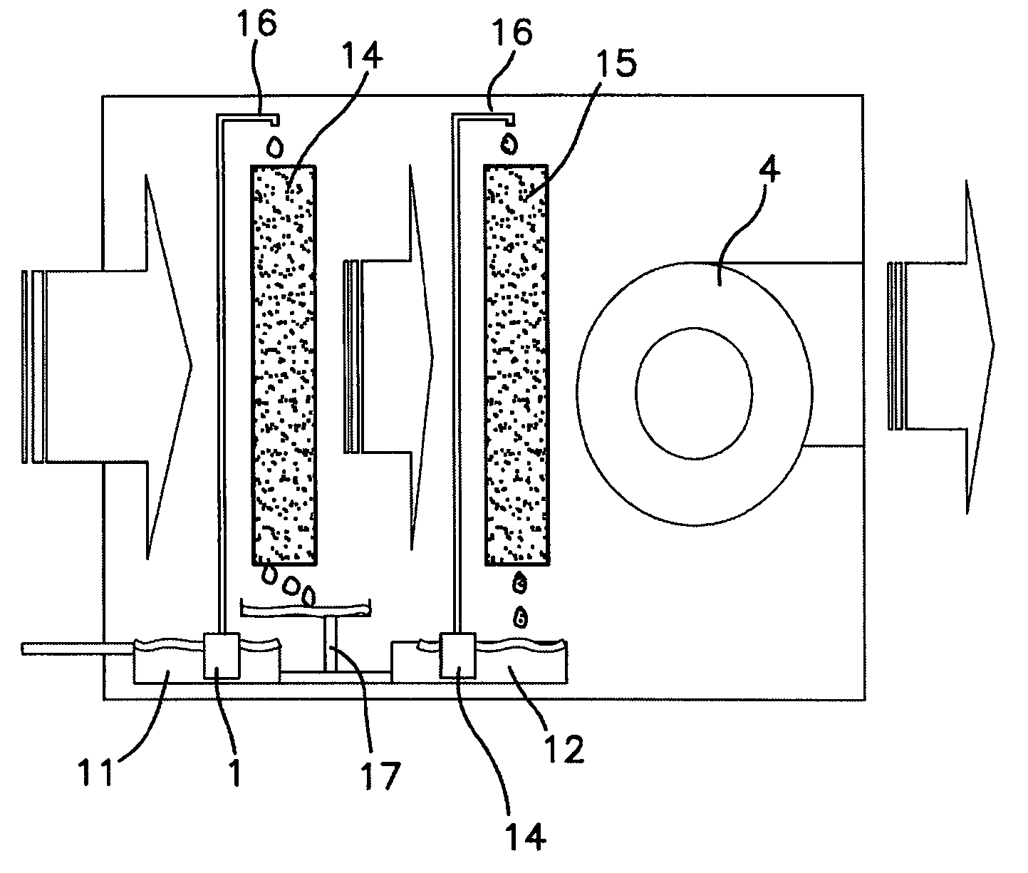
[0041]Most conventional evaporative air coolers depend on humidification with constant wet bulb temperature or constant adiabatic line with a single stage cooling and single water tank, resulting in unstable supply air temperate. The present invention uses the constant adiabatic process at first stage cooling up to the desired relative humidity then uses the second stage to stabilize supply air temperature by stabilizing water tank temperature. The second stage also reduces the wet bulb and dry bulb temperatures, depending on the desired capacity of cooling coil. The present invention has a number of features and advantages that can be seen in the attached drawing figures:

[0042]Tanks are Isolated from External Body:

[0043]Our device have two separate water tanks isolated from external body, a second stage tank inside the first stage tank (or separated), connected by the water distribution chambers.

[0044]Supply Air is at a Lower Temperature in Summer:

[0045]The device depends on two st...


PUM


Abstract

An outdoor air cooler with two stages includes a first stage for cooling and humidification with constant wet bulb temperature. The air cooler has a first stage pump circulating water over the first stage evaporative cooling media operating at conditions having a constant adiabatic wet bulb temperature line. The first stage tank is supplied with water from external source. The second stage includes a second set of evaporative cooling media using water from the first stage media, which is equal to or lower than outdoor air wet bulb temperature. The temperature of air leaving the second stage evaporative media follows the adiabatic wet bulb temperature line toward the second stage tank water temperature thereby cooling humidifying the treated air to stable wet and dry bulb temperatures.

Description

CROSS-REFERENCE TO RELATED APPLICATIONS[0001]This application claims the benefit under 35 U.S.C. §119 of Saudi Arabian Patent Application Nos. 109300247 and 109300248, filed Apr. 26, 2009, which are hereby incorporated by reference in their entirety.FIELD OF THE INVENTION[0002]The present invention relates to a direct, water evaporative-type desert cooler with optional cooling coil and heating coils. In particular, the invention relates to a water evaporative type desert cooler that can provide supply air with dry bulb and wet bulb temperature close or lower than outdoor air wet bulb temperature.BACKGROUND OF THE INVENTION[0003]There are a number of different methods for cooling a flowing stream of air. Indirect evaporative cooling invented in the mid-seventies (see, for example, Schlom, et al., U.S. Pat. Nos. 4,023,949 and 6,385,987) uses the latent heat of the evaporation of water to remove heat from the air.[0004]Direct evaporative coolers on the other hand, also known as swamp c...

Claims


Application Information

Patent Timeline
Patent Type & Authority Applications(United States)
IPC IPC(8): F25B13/00F28D5/00F25D21/14
CPCF24F5/0035Y02B30/545F28D5/00F24F6/043Y02B30/54
Inventor AL WATBAN, ALAA ABDULKAREEM
Owner AL WATBAN ALAA ABDULKAREEM
Why Eureka
Try Eureka