Selectable effect warhead

a warhead and selectable technology, applied in the field of weapons, can solve the problems of collateral damage, unintended damage or destruction of life or property near the target, and the material is more vulnerable to fragments and blast overpressure, so as to reduce the collateral

Active Publication Date: 2010-11-11
LOCKHEED MARTIN CORP
View PDF31 Cites 23 Cited by
  • Summary
  • Abstract
  • Description
  • Claims
  • Application Information

AI Technical Summary

Benefits of technology

[0009]According to the principles of the present invention, the above-described selectability of the mode of operation of a munition allows the weapon to be used against a broad target set like a general purpose bomb, but when the need arises for reduced collateral effects, the fragments can be selectively eliminated.

Problems solved by technology

Materiel is more vulnerable to fragments and structures are more vulnerable to blast overpressure.
Personnel are vulnerable to both.
This overmatch has driven our adversaries to attempt to seek cover in civilian populations where our rules of engagement limit our ability to engage them.
Collateral damage is the unintended damage or destruction of life or property near a target.
The elimination of the fragments results in a warhead with a primarily blast damage mechanism.
However, the permanent elimination of fragments limits the target set against which the weapon is useful and in essence a niche weapon.
It increases the logistic trail and mission loadout complexity.

Method used


Image

  • Selectable effect warhead
  • Selectable effect warhead
  • Selectable effect warhead

Examples


Embodiment Construction

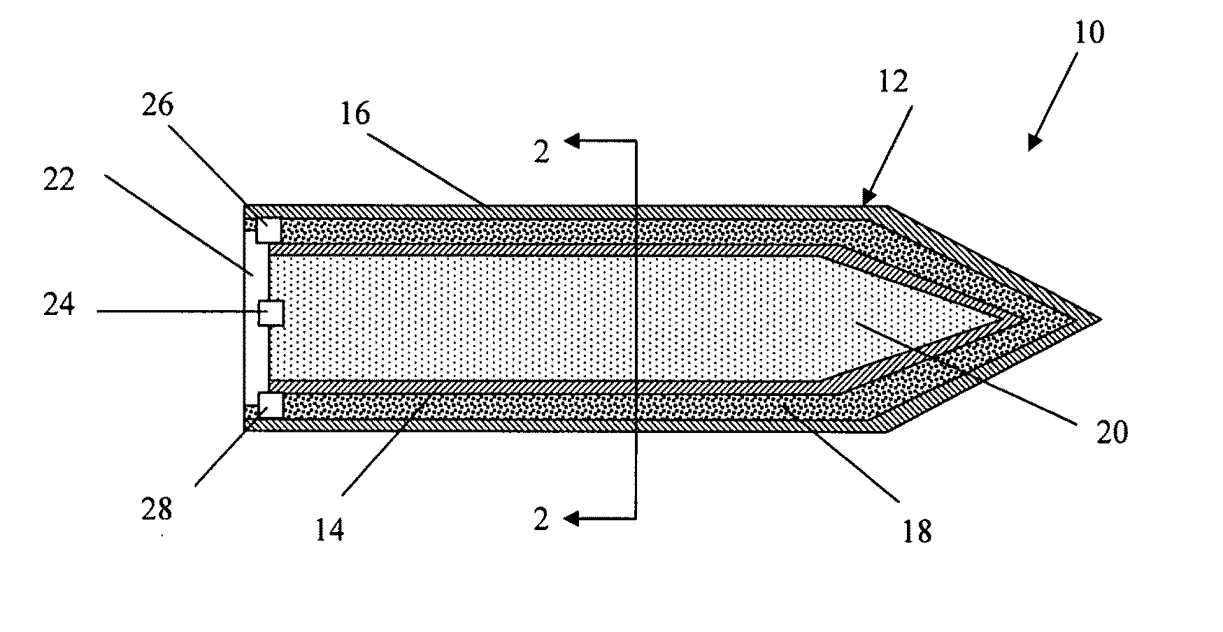
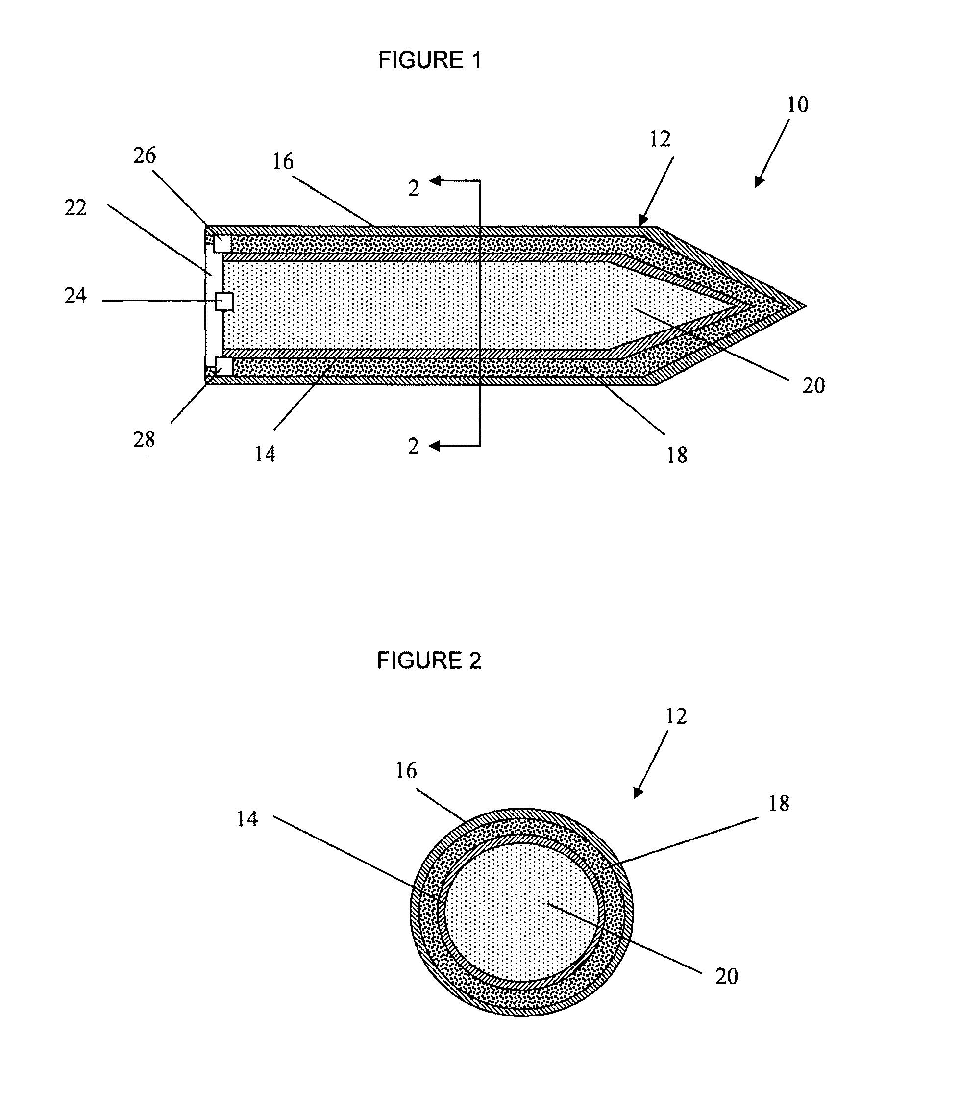
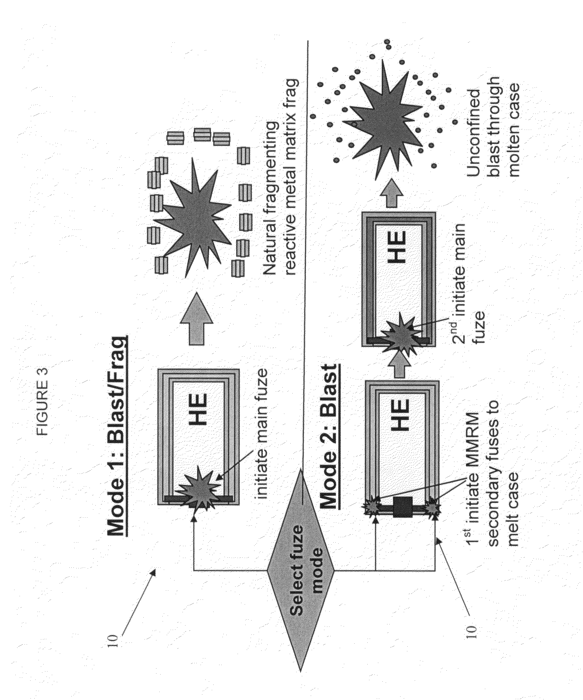
[0016]FIGS. 1-2 illustrates an exemplary munition 10 formed according to one embodiment of the present invention. As illustrated, the munition 10 may be in form of a warhead comprising a casing 12 carrying an explosive payload 20. The shape of the casing 12 is not limited to the illustrated embodiment, and may have any suitable geometry and / or size. The casing 12 may optionally include an inner and / or outer liner or shield 14 and / or 16, respectively. The liner(s) or shield(s) may be provided as a thermal shield. The liner(s) and / or shield(s) can be formed from any suitable material(s). By way of non-limiting example, the shields can be formed from a thermoplastic. Thermoplastics such as polytetrafluoroethylene (PTFE) or polyetheretherketone (PEEK) can be utilized. The linear(s) and / or shield(s) 14, 16 serve to, at least in part, prevent the transfer of thermal energy to the payload 20 of a magnitude that could cause unwanted detonation thereof.

[0017]The main component of the casing ...


PUM


Abstract

A munition includes a casing, the casing formed at least in part from a material comprising (i) a meltable or phase-changing material, and (ii) an energetic material; an explosive payload contained within the casing; and a fuze arrangement, the fuze arrangement comprising a main fuze configured and arranged to ignite the high explosive, and at least one secondary fuze configured and arranged to cause the casing material to melt or undergo a phase change. A method of selectively altering the mode of operation of a munition includes: forming a casing, the casing comprising a material comprising (i) a meltable or phase-changing material, and (ii) an energetic material; introducing an explosive payload into the casing; providing a fuze arrangement comprising a main fuse and at least one secondary fuze configured and arranged to cause the casing material to melt or undergo a phase change; and selectively activating the main fuze and the at least one secondary fuze in a manner that provided at least a first and a second mode of operation, the first mode of operation comprising blast coupled with fragmentation effects, and the second mode of operation comprising mainly blast effects.

Description

[0001]This application claims priority, pursuant to 35 U.S.C. §119, to U.S. Provisional Patent Application No. 60 / 809,046 filed May 30, 2006, the entire content of which is incorporated herein by reference.FIELD OF THE DISCLOSURE[0002]The present disclosure relates to arrangements, compositions, as well as design and fabrication techniques relating to munitions.BACKGROUND OF THE INVENTION[0003]In the discussion of the state of the art that follows, reference is made to certain structures and / or methods. However, the following references should not be construed as an admission that these structures and / or methods constitute prior art. Applicant expressly reserves the right to demonstrate that such structures and / or methods do not qualify as prior art.[0004]A conventional blast-frag warhead inflicts damage by two primary methods. The first is the overpressure generated from the detonation of an explosive fill. The second is the formation and acceleration of metal fragments from the wa...

Claims


Application Information

Patent Timeline
Patent Type & Authority Applications(United States)
IPC IPC(8): F42B12/76F42B12/20
CPCF42B12/207F42B12/76F42B12/74F42B12/36
Inventor SHERIDAN, EDWARD W.HUGUS, GEORGE D.METZGER, JOSEPH G.
Owner LOCKHEED MARTIN CORP
Why Eureka
Try Eureka