Agricultural Seeder Implement

a technology of implements and implements, applied in the direction of agricultural tools and machines, drags, furrow making/covering, etc., can solve the problems of uneven seed placement depth and non-uniform seed rows

Active Publication Date: 2010-11-11
VADERSTAD LLC
View PDF39 Cites 62 Cited by
  • Summary
  • Abstract
  • Description
  • Claims
  • Application Information

AI Technical Summary

Benefits of technology

[0007]This Summary is provided to introduce a selection of concepts in a simplified form that are further described below in the Detailed Description. This Summary is not intended to identify key features or essential features of the claimed subject matter, is not intended to describe each disclosed embodiment or every implementatio

Problems solved by technology

This results in a non-uniform seed row

Method used


Image

  • Agricultural Seeder Implement
  • Agricultural Seeder Implement
  • Agricultural Seeder Implement

Examples


Embodiment Construction

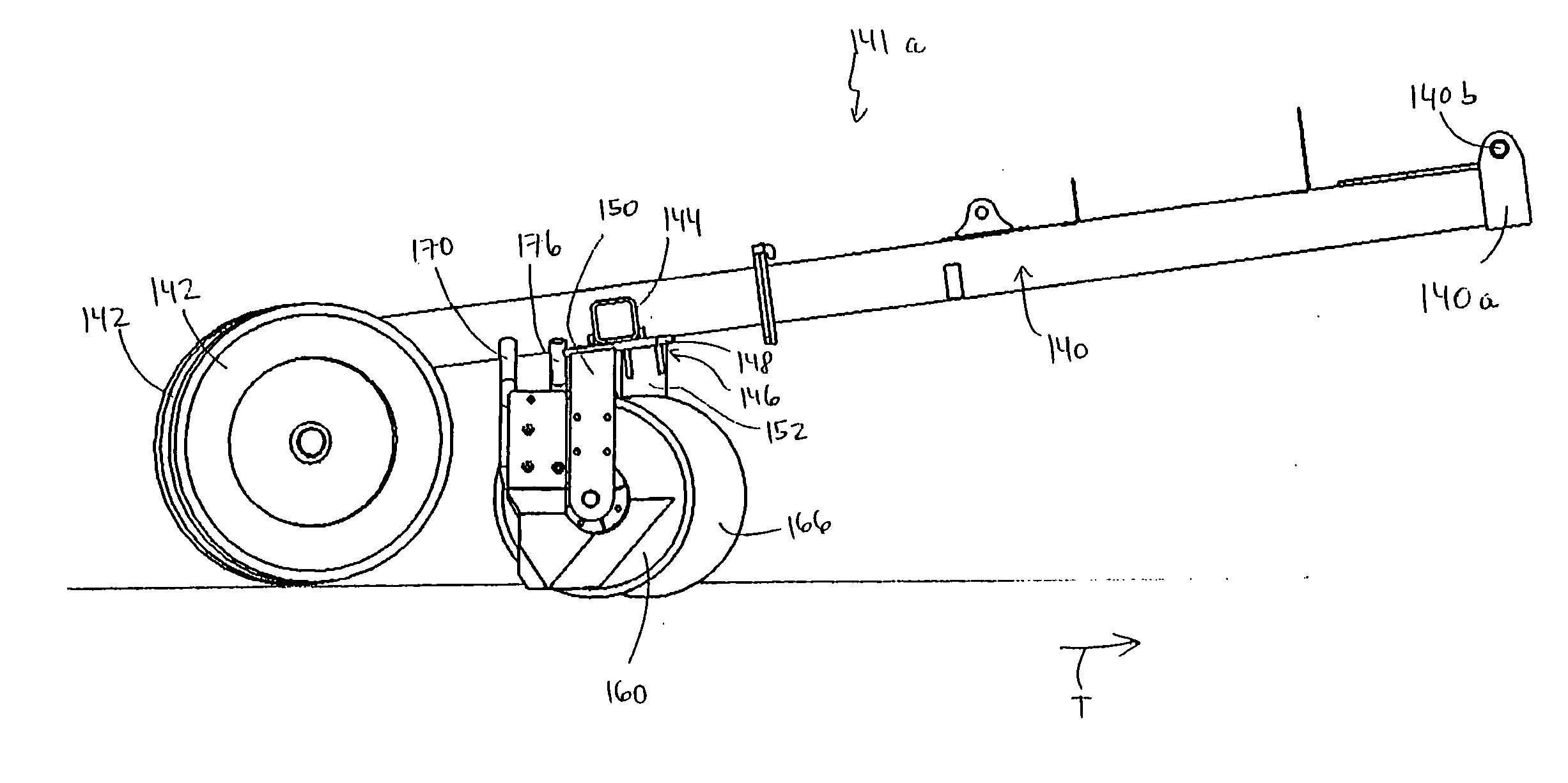
[0029]In an exemplary twin disk drill seeder implement, offsetting the disks relative to the longitudinal orientation of the implement mitigates the problem of soil and residue pickup by the disks. The soil is no longer carried around a disk; rather, it is released from the disks as it is lifted between the disks. This results in a uniform seed row and seeding depth.

[0030]Instead of aligning the disks in a mirror image relationship laterally across the implement, the disks of each pair are offset in the implement's longitudinal orientation. The two paired disks are held on a common fork arranged so that the disks displace soil towards each other as they are drawn across the ground. The disks are offset from 0.25 to 8 inches, relative to one another, in the longitudinal direction. In other words, the trailing edge of one disk is farther behind the trailing edge of the other disk, by 0.25 to 8 inches. The disks rotate during engagement with the ground as the implement moves over the g...


PUM


Abstract

A seeder implement (125) includes a fork (146) having a first spindle support arm (150) that supports a first spindle (164) and a second spindle support arm (152) that supports a second spindle (168). A first disk (160) is supported on the first spindle (164), wherein the first spindle (164) is oriented in a first orientation and at a first acute angle relative to a lateral line. The first disk (160) is oriented at a second acute angle relative to the ground surface. A second disk (166) is supported on the second spindle (168), wherein the second spindle (168) is oriented in a second orientation and at a third acute angle relative to the lateral line. The second disk (166) is oriented at a fourth acute angle relative to the ground surface. The first disk (160) is longitudinally offset ahead of the second disk (166), and there are no structural components between the first and second disks (160, 166) other than the first and second spindles (164, 168). In one embodiment, a packing wheel (142) is disposed to close and compact furrows opened by the disks (160, 166) and is disposed in the same orientation as one of the disks (160, 166).

Description

BACKGROUND[0001]Agricultural implements for opening furrows in the ground and depositing seed therein are well known. One such agricultural apparatus is disclosed in U.S. Pat. No. 7,216,596 B2, which is incorporated by reference herein. Such implements can form a plurality of furrows extending longitudinally along the direction of travel of the implement over the ground. Each furrow is formed by a disk drill that is rotatably mounted on the implement and cuts into the ground as the implement passes through the field. The disk drill may be disposed at an angle relative to the direction of travel, and also may be disposed at an angle relative to a direction normal to the ground over which it traverses (e.g., vertical, relative to a horizontally flat field). On one such implement design, such disk drills are arranged in pairs laterally across the implement and have one soil packing wheel disposed behind each pair of disks. In such a pair of these disks, the disks have the same diameter...

Claims


Application Information

Patent Timeline
IPC IPC(8): A01C5/06A01B5/00A01B5/04A01C5/00
CPCA01C5/064A01C5/066A01C5/068
Inventor BREKER, EUGENEGUST, JAKEJUSTESEN, DARRYLOBERLANDER, JACK
Owner VADERSTAD LLC
Why Eureka
Try Eureka