Wafer container

a container and container body technology, applied in the field of wafer containers, can solve the problems of leakage of magnetic flux, large door thickness, air tightness defect, etc., and achieve the effect of reducing the thickness of the door and reducing the generation of particles

Active Publication Date: 2010-11-11
CHIU MING CHIEN +3
View PDF6 Cites 24 Cited by
  • Summary
  • Abstract
  • Description
  • Claims
  • Application Information

AI Technical Summary

Benefits of technology

[0008]In wafer container of prior art, there are problems such as defective effect of air tightness, larger thickness of the door, and leakage of magnetic flux. One primary objective of the present invention is thus to provide a wafer container using magnet in the is lock-fastening method, around the inner surface of the door of the wafer container being disposed with magnet and at the inner edge of the opening of the container body being disposed with component that can be attracted by the magnet, metal bar for example. By using this method of lock-fastening, there is no need to dispose the cam and the sliding devices in the door and the thickness of the door can thus be effectively reduced. Moreover, without the operation between the cam and the sliding devices, the particle generation can also be reduced.
[0009]Another primary objective of the present invention is to provide a wafer container using magnet in the lock-fastening method. Around the inner surface of the door of the wafer container is disposed with magnet, on the outer surface of which a seal element is further disposed, and at the inner edge of the opening of the container body is disposed with a metal bar. Therefore, when the door and the container body are lock-fastened to each other, the seal element is sandwiched between the magnet and the metal bar for achieving better effect of air tightness of the wafer container.
[0010]Still another primary objective of the present invention is to provide a wafer container using magnet in the lock-fastening method. Around the inner surface of the door of the wafer container is disposed with magnet deployed in a magnetic yoke with recessed cross section. Therefore the magnetic flux of the magnet can be effectively guided toward or focused on the inner edge of the opening of the container body and the leakage of magnetic flux in other directions can be prevented for firmly lock-fastening the door and the container body to each other and also enhancing the stability of circuit of the wafers in the container body.
[0012]And another wafer container according to the present invention comprises a container body and a door. In this embodiment, the magnet is disposed on the container body and the magnetic member is disposed on the door, with the design of which the door and the container body can also be lock-fastened to each other. On the outer surface of the magnet of the wafer container of the present invention is also disposed with a seal element. Therefore when the door and the container body are lock-fastened to each other, the seal element is firmly sandwiched between the magnet and the magnetic member and the problem of defective effect of air tightness of the wafer container can thus be eliminated.

Problems solved by technology

In wafer container of prior art, there are problems such as defective effect of air tightness, larger thickness of the door, and leakage of magnetic flux.

Method used


Image

  • Wafer container
  • Wafer container
  • Wafer container

Examples


Embodiment Construction

[0028]In order to disclose the skills applied in, the objectives of, and the effects achieved by the present invention in a more complete and clearer manner, preferred embodiments are herein described below in detail with related drawings disclosed for reference.

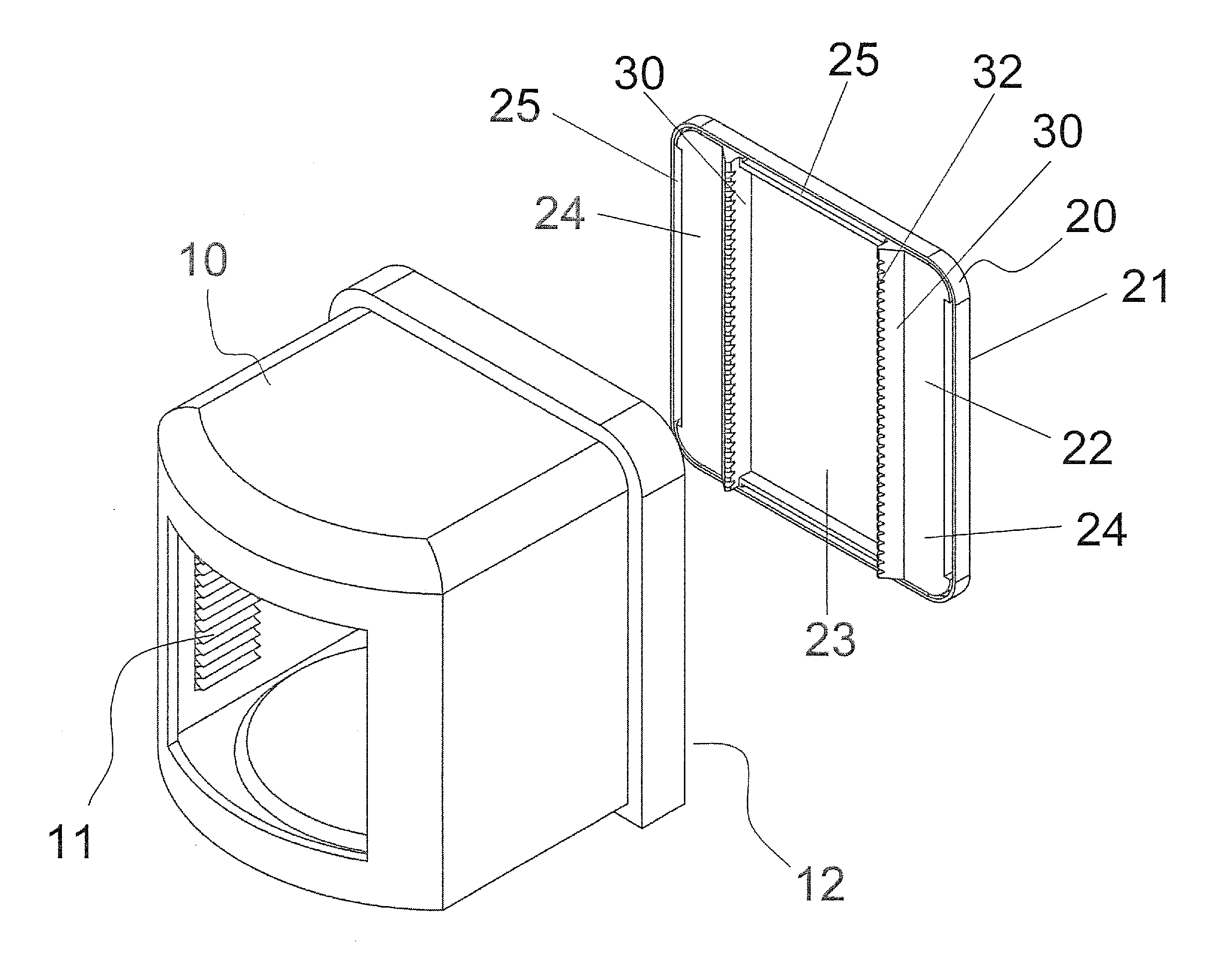
[0029]First, referring to FIG. 3, which is a view of the first type of wafer container of the present invention. The wafer container is a front opening unified pod (FOUP) that includes a container body 10 and a door 20. Inside the container body 10 is an accommodating space within which a plurality of slots 11 are disposed for supporting a plurality of wafers, and an opening 12 is formed on one sidewall of the container body 10 for importing and exporting the plurality of wafers. The door 20 includes an outer surface 21 and an inner is surface 22. Wherein, around the central area of the inner surface 22 of the door 20 is disposed with a recess 23, and the recess 23 can separate the inner surface 22 of the door 20 into two pl...


PUM


Abstract

A wafer container includes a container body, the internal of which is disposed with a plurality of slots for supporting a plurality of wafers and an opening is formed on one sidewall of which, and a door, which is joined with opening of the container body for protecting the plurality of wafers in the container body, the characteristic in that: a magnetic member is formed at the inner edge of the opening of the container body and a magnet is disposed at the inner surface of the door corresponding to the magnetic member, the magnet being disposed in a magnetic yoke with recessed cross section, with the design of which the magnet on the door attracts the magnetic member at the opening of the container body for the door and the container body to be lock-fastened to each other.

Description

BACKGROUND OF THE INVENTION[0001]1. Field of the Invention[0002]The present field of the invention is related to a wafer container, and more particularly, to a wafer container using magnet for sealing and lock-fastening the door and the container body.[0003]2. Description of the Prior Art[0004]The semiconductor wafers are transferred to different stations to apply the various processes in the required equipments. A sealed container is provided for automatic transfer to prevent the is pollution from occurring during transferring process. A front opening unified pod (FOUP) according to the conventional prior art includes a container body and a door. The container body is disposed with a plurality of slots for horizontally supporting a plurality of wafers, and an opening is located on a sidewall of the container body for importing and exporting the wafers. The door includes an outer surface and an inner surface and is joined with the opening of the container body via the inner surface ...

Claims


Application Information

Patent Timeline
Patent Type & Authority Applications(United States)
IPC IPC(8): H01L21/673
CPCH01L21/67373H01L21/67369Y10S206/818
Inventor CHIU, MING-CHIENLU, PAO-YILIN, CHIN-MINGHUNG, KUO-CHUN
Owner CHIU MING CHIEN
Why Eureka
Try Eureka