Co-injection molded chair

a chair and injection molding technology, applied in the field of chairs, can solve problems such as prone to material failure, and achieve the effect of reducing the need for external cooling and reducing the cycle tim

Inactive Publication Date: 2010-11-11
KNOLL INC
View PDF16 Cites 14 Cited by
  • Summary
  • Abstract
  • Description
  • Claims
  • Application Information

AI Technical Summary

Benefits of technology

[0011]In addition, because the endothermic blowing agents absorb hea...

Problems solved by technology

This chair does not have a back support ...

Method used


Image

  • Co-injection molded chair
  • Co-injection molded chair
  • Co-injection molded chair

Examples


Embodiment Construction

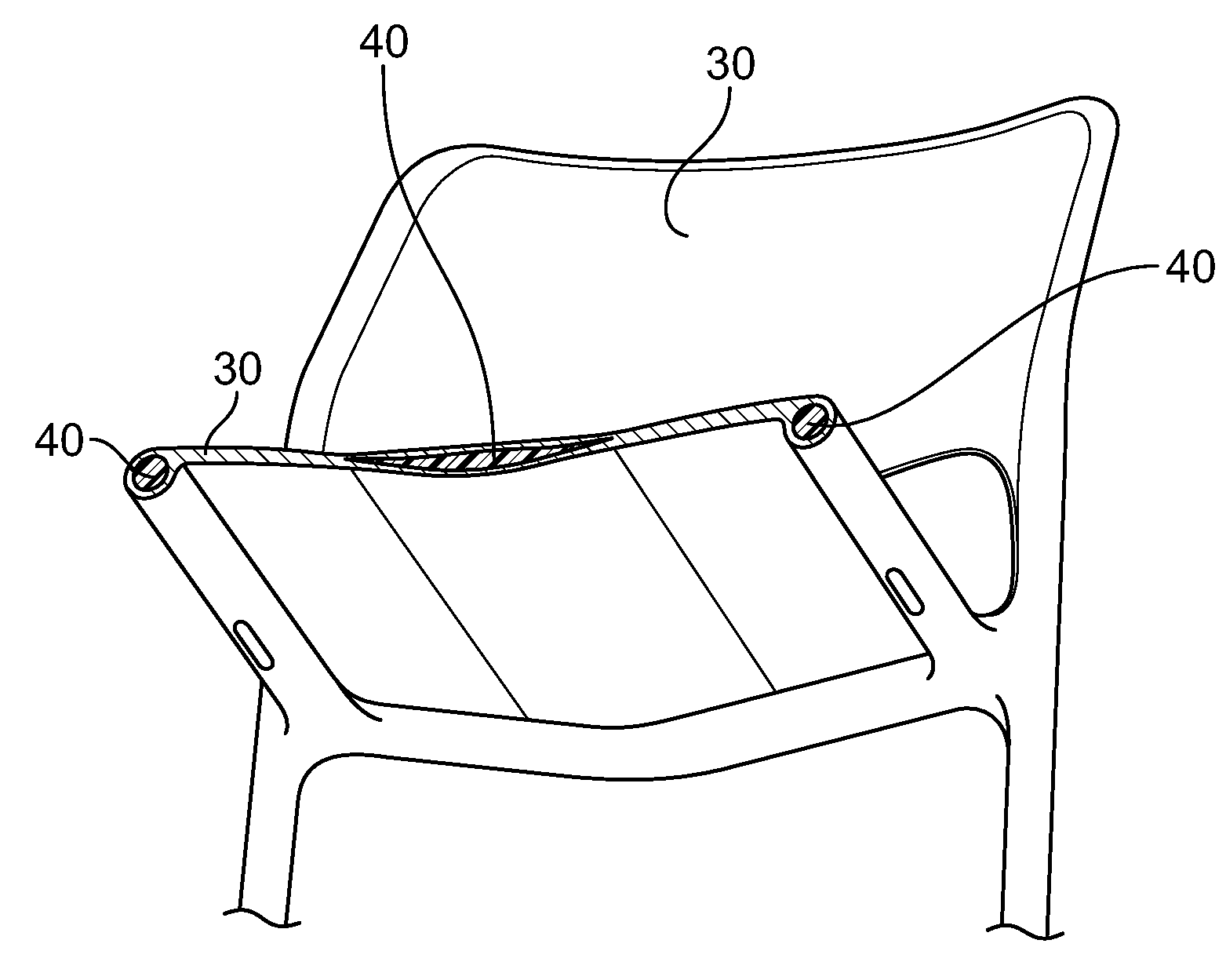
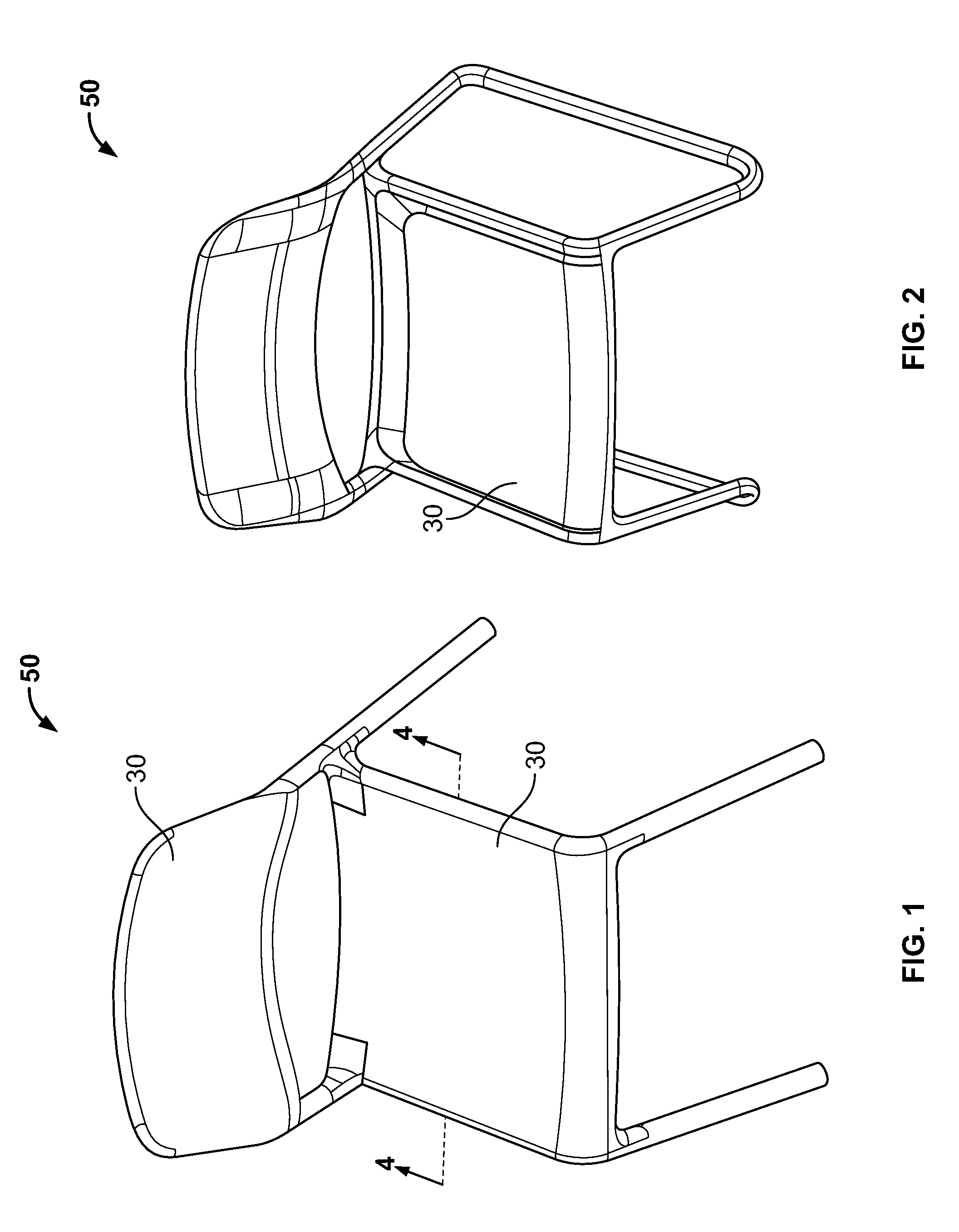
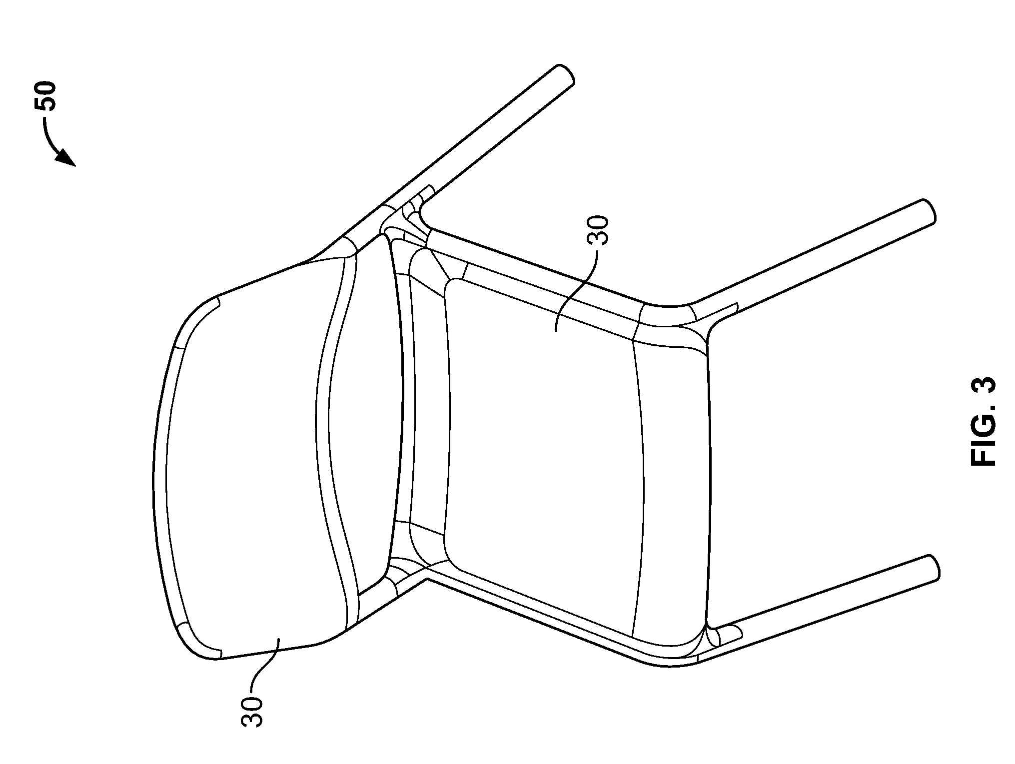
[0018]Chairs 50 made by the co-injection molding process herein described are shown in FIGS. 1 through 3. As used herein, the term co-injection molding is meant to refer to a process by which two like or dissimilar plastics (e.g., a skin or outer material 30 and a core or inner material 40) originating from different sources (e.g., injection units 12, 14) are injected into a single mold 16 during a single cycle. The co-injection of the plastics may be sequential or simultaneous, as further described below. Co-injection molding is different from insert molding or overmolding.

[0019]Co-injecting the plastics may be done using a substantially sequential process. Typically, plastics are injected through a co-injection manifold and into the mold at temperatures around 300-600 degrees Fahrenheit. The co-injection manifold 10 is typically located between injection units or barrels 12, 14 and a mold 16. A typical co-injection manifold 10 is fixed to the injection units 12, 14. Suitable co-in...


PUM

PropertyMeasurementUnit
Fractionaaaaaaaaaa
Fractionaaaaaaaaaa
Fractionaaaaaaaaaa

Abstract

The invention is directed to an article made from co-injection molding. The article has an inner material and an outer material. The inner material has a blowing agent uniformly distributed throughout the inner material. The outer material surrounds the inner material. The use of the blowing agent in the inner material produces a repeatable and consistent structure, as the blowing agent is uniformly activated through the product.

Description

FIELD OF THE INVENTION[0001]The present invention is directed to a chair which is manufactured from a co-injection molding process, and more particularly to a chair which is suitable for use in professional environments such as an office.BACKGROUND OF THE INVENTION[0002]Molded chair shells have been well known in the art for some time. A typical example of a molded chair shell is disclosed in U.S. Pat. No. 3,669,496, which includes a single, molded piece that forms the seat and the seat back. The chair further requires a frame, i.e., a back support, to which the molded piece is attached. Another example of a molded chair is disclosed in U.S. Pat. No. 3,751,109, which shows a single, molded piece with legs attached at the bottom. This chair does not have a back support and therefore may be prone to material failure.[0003]U.S. Pat. No. 5,985,188 discloses a method and mold design for forming a molded chair seat portion and chair back support portion using air counterpressure and two d...

Claims


Application Information

Patent Timeline
IPC IPC(8): A47C5/12B29C45/16
CPCA47C5/12B29C44/0461B29L2031/771B29K2105/04B29L2031/443B29C45/1642
Inventor DESKEVICH, ADAM DANIELVAN HEKKEN, HENDRIK RICHARD
Owner KNOLL INC
Why Eureka
Try Eureka