Magnetic sensor and method for producing the same

Active Publication Date: 2010-11-11
ALPS ALPINE CO LTD
View PDF1 Cites 3 Cited by
  • Summary
  • Abstract
  • Description
  • Claims
  • Application Information

AI Technical Summary

Benefits of technology

[0038]According to the present invention, an electrode section having a larger width than the extension region is preferably formed at a tip of the extension region; and the contact hole is preferably formed within a region of the electrode section such that a portion of the electrode section is left aroun

Problems solved by technology

In this case, additional material is required for forming th

Method used


Image

  • Magnetic sensor and method for producing the same
  • Magnetic sensor and method for producing the same
  • Magnetic sensor and method for producing the same

Examples


Example

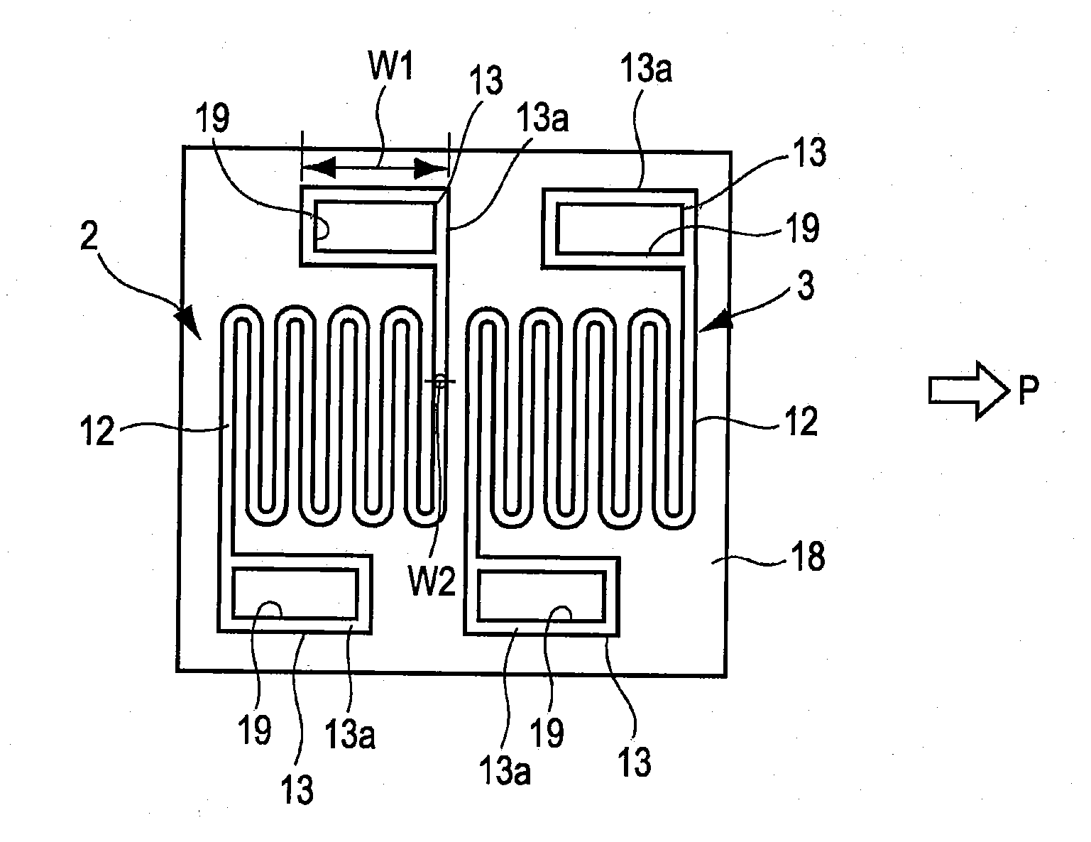
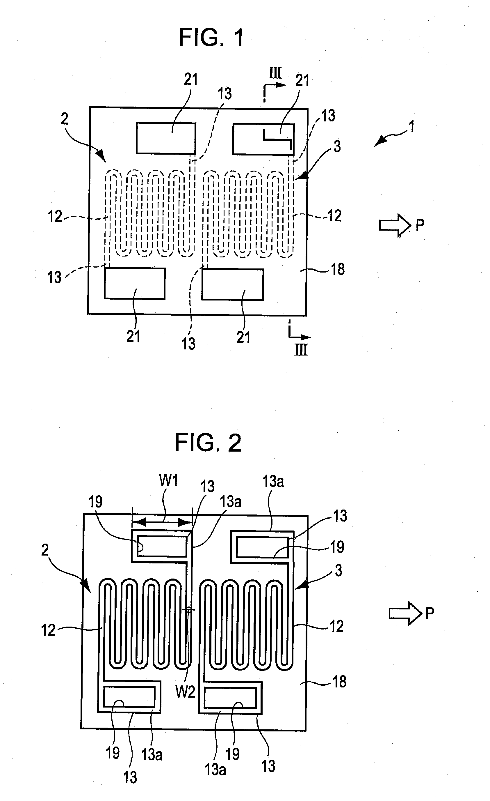
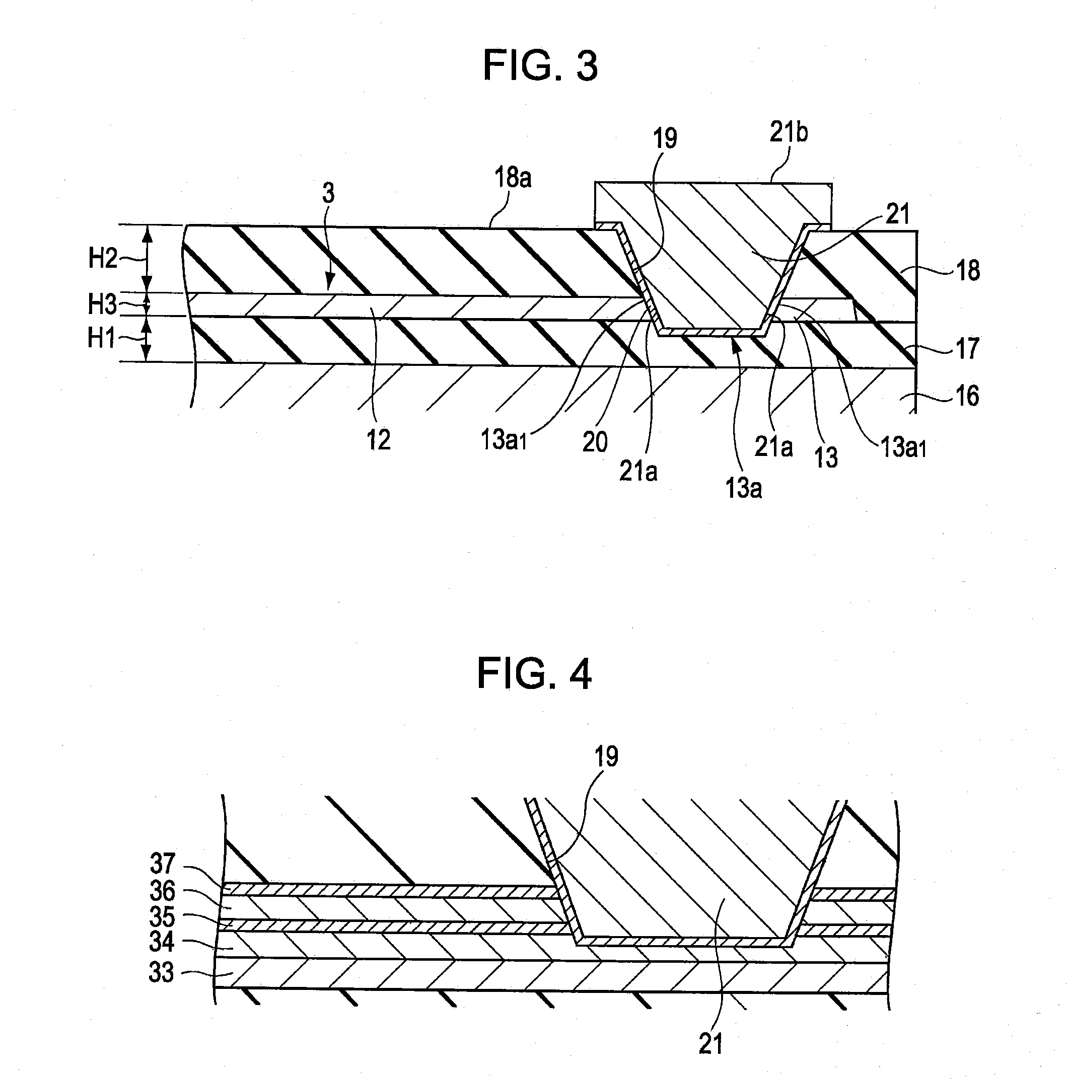
[0053]FIG. 1 is a plan view illustrating a magnetic sensor according to an embodiment, in particular, a portion of the magnetic sensor corresponding to magnetoresistive elements. FIG. 2 is a plan view of the portion corresponding to the magnetoresistive elements in the state in which electrode pads and an insulation layer have been removed from the configuration illustrated in FIG. 1. FIG. 3 is a partial enlarged section of the magnetic sensor, the section being taken along line illustrated in FIG. 1 in the height direction and viewed in the direction of arrows illustrated in FIG. 1. FIG. 4 is a partial enlarged section of a magnetic sensor having a configuration that is different from the configuration illustrated in FIG. 3. FIG. 5 is a diagram for illustrating the relationship between electrical resistance and the pinned magnetization direction of a pinned magnetic layer and the magnetization direction of a free magnetic layer of a magnetoresistive element. FIG. 6 is a sectional v...


PUM

PropertyMeasurementUnit
Magnetic fieldaaaaaaaaaa
Electrical resistanceaaaaaaaaaa
Shapeaaaaaaaaaa

Abstract

A magnetoresistive element includes, in plan view, an element section and an extension region extending from an end portion of the element section; and an insulation layer is formed on the element section and the extension region. A contact hole having a recessed shape, penetrating through the insulation layer, and extending at least to the extension region is formed; an electrode pad is formed in the contact hole; a surface of the electrode pad is exposed to outside; and the electrode pad is electrically connected to the extension region. The element section and the extension region are integrally formed so as to have an identical layer configuration employing a magnetoresistive effect in which electrical resistance varies in response to external magnetic fields.

Description

CLAIM OF PRIORITY[0001]This application is a Continuation of International Application No. PCT / JP2009 / 050526 filed on Jan. 16, 2009, which claims benefit of Japanese Patent Application No. 2008-013341 filed on Jan. 24, 2008. The entire contents of each application noted above are hereby incorporated by reference.BACKGROUND OF THE INVENTION[0002]1. Field of the Invention[0003]The present invention relates to a magnetic sensor in which the connection between an electrode pad and an element section can be stabilized and the production process of the magnetic sensor can be simplified; and a method for producing such a magnetic sensor.[0004]2. Description of the Related Art[0005]A magnetic sensor including a magnetoresistive element is used as, for example, a geomagnetic sensor or an open / close detecting sensor. The electrical resistance of such a magnetoresistive element varies in response to the intensity of external magnetic fields.[0006]FIGS. 12A to 14B illustrate steps of a method f...

Claims


Application Information

Patent Timeline
IPC IPC(8): G01R33/02H05K13/00
CPCB82Y25/00G01R33/093Y10T29/49002H01L43/12H01L43/08H10N50/10H10N50/01
Inventor ANDO, HIDETOTAKABATAKE, TAKASHISAITO, TATSUYA
Owner ALPS ALPINE CO LTD
Why Eureka
Try Eureka