Dual band antenna arrangement

Active Publication Date: 2010-11-11
INTEL CORP
View PDF7 Cites 9 Cited by
  • Summary
  • Abstract
  • Description
  • Claims
  • Application Information

AI Technical Summary

Benefits of technology

[0012]In use, elements of said third column being operative in said first frequency band may be fed by the signal to said elements of said first column being operative in said first frequency band offset by a phase angle α, and said elements of said second column and elements of said third column being oper

Problems solved by technology

Although this solution has the drawback that the frequency bands FB1 and FB2 will couple to each other due to the closeness of the parts making up the antenna element, space savings often

Method used


Image

  • Dual band antenna arrangement
  • Dual band antenna arrangement
  • Dual band antenna arrangement

Examples


Example

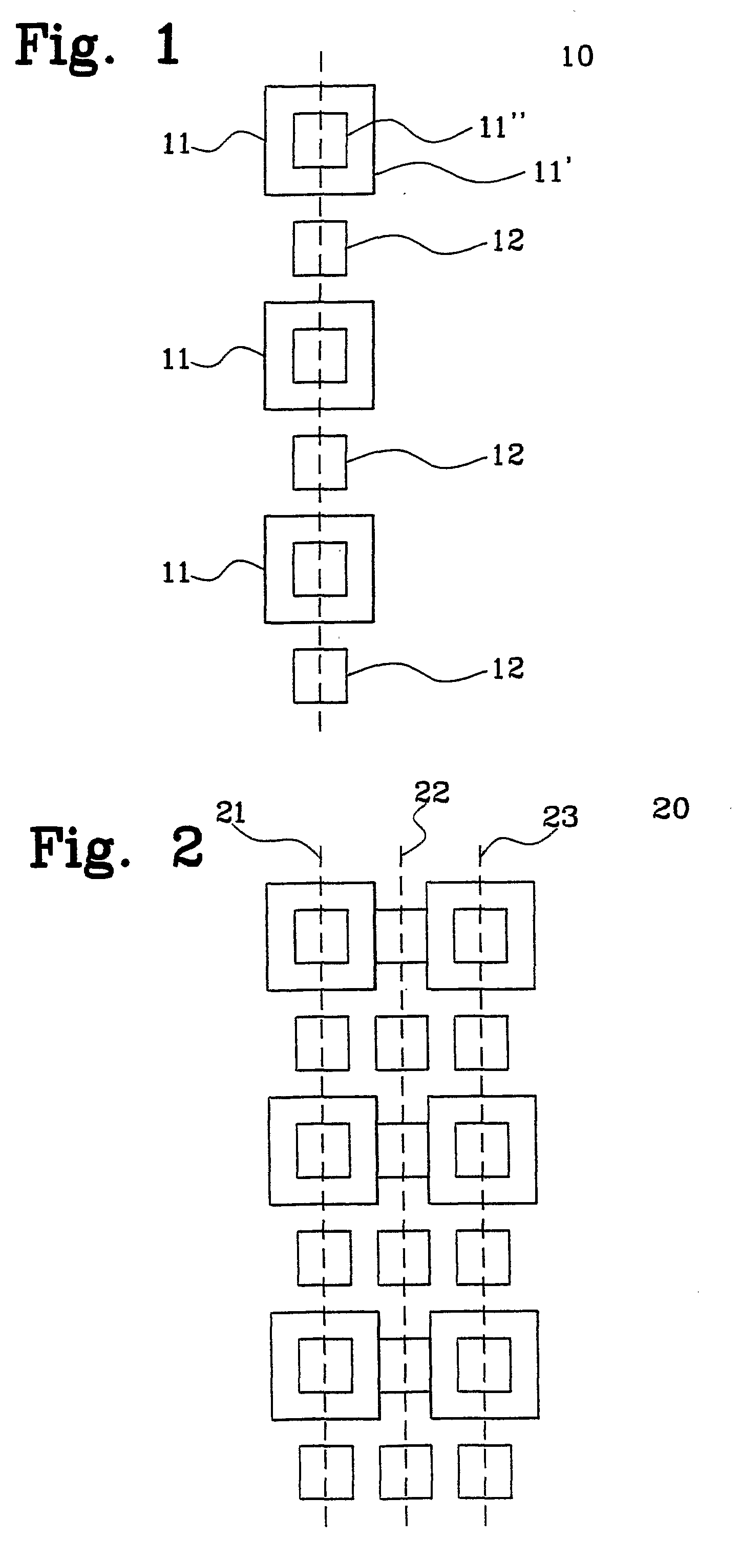
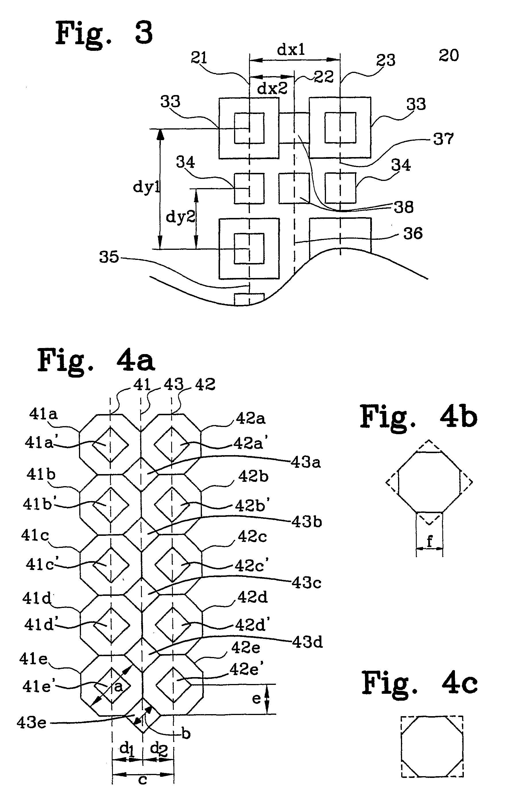
[0020]As was mentioned above, FIG. 2 shows a prior art arrangement for azimuth control of a beam radiated from an antenna arrangement. As also has been disclosed above, the described arrangement suffers from the disadvantage that an ambiguity regarding the direction of arrival of a received signal frequently arises. This is true in the high-frequency band FB2 and in the low-frequency band FB1. The reason for this will be explained in connection to FIG. 3, which shows a portion of an arrangement of FIG. 2 more in detail.

[0021]In FIG. 3 is shown the upper portion of the arrangement of FIG. 2, i.e., the upper portion of an arrangement comprising two columns of elements 21, 23, each comprising a set of single band elements 34, and a set of dual band elements 33, said elements 33, 34 being aligned along parallel symmetry axes 35, 37. Further, an intermediate column 22 of single band antenna elements 38, aligned along a symmetry axis 36, which is parallel to said axes 35, 37, is imposed b...


PUM


Abstract

The present invention relates to an antenna arrangement comprising a first and third set of antenna elements, being arranged as a first and third column and aligned along a first and third symmetry axis, respectively, each column comprising elements being operative in a first frequency band (f1) and elements being operative in a second frequency band (f2). The antenna arrangement further comprises a second set of antenna elements, being arranged as a second intermediate column along a second symmetry axis, said second symmetry axis being parallel to said first and third symmetry axes, and being operative in said second frequency band (f2), wherein the ratio of said second centre frequency (f2) to said first centre frequency (f1) is in the range 1.5 to 3. The distance between said first and third symmetry axes is less than or equal to 0.6 times the wavelength of said first centre frequency (f1), and the distance between said second and said first and third symmetry axis, respectively, is less than or equal to 0.6 times the wavelength of said second centre frequency (f2).

Description

FIELD OF THE INVENTION[0001]The present invention relates to an antenna arrangement for receiving and / or transmitting electromagnetic signals in at least two spaced-apart frequency bands, especially for mobile communication systems, as defined in the preamble of claim 1.BACKGROUND OF THE INVENTION[0002]Antenna arrays are commonly used for transmitting and receiving RF (Radio Frequency) signals in mobile communication systems and are, in such communication, normally dedicated to a single frequency band or sometimes two or more frequency bands. Single frequency band antennas have been used for a long time and normally include a number of antenna elements arranged in a vertical column. A second column of antenna elements needs to be added next to the first column if a network operator decides to add another frequency band using single frequency band antennas.[0003]Due to the rather substantial space requirements of single band columns of antenna elements, and since such an arrangement ...

Claims


Application Information

Patent Timeline
IPC IPC(8): H01Q21/08H01Q5/42
CPCH01Q1/246H01Q5/42H01Q21/062H01Q21/061
Inventor LINDMARK, BJORNUDDIN, JESPER
Owner INTEL CORP
Why Eureka
Try Eureka