

Capacitive touch panel and method for detecting touched input position on the same
- Summary
- Abstract
- Description
- Claims
- Application Information
AI Technical Summary
Benefits of technology
Problems solved by technology
Method used
Image

Examples
Embodiment Construction
[0050]An embodiment for implementing the present invention is hereunder described by reference to the drawings. The present invention is not limited to the embodiment.
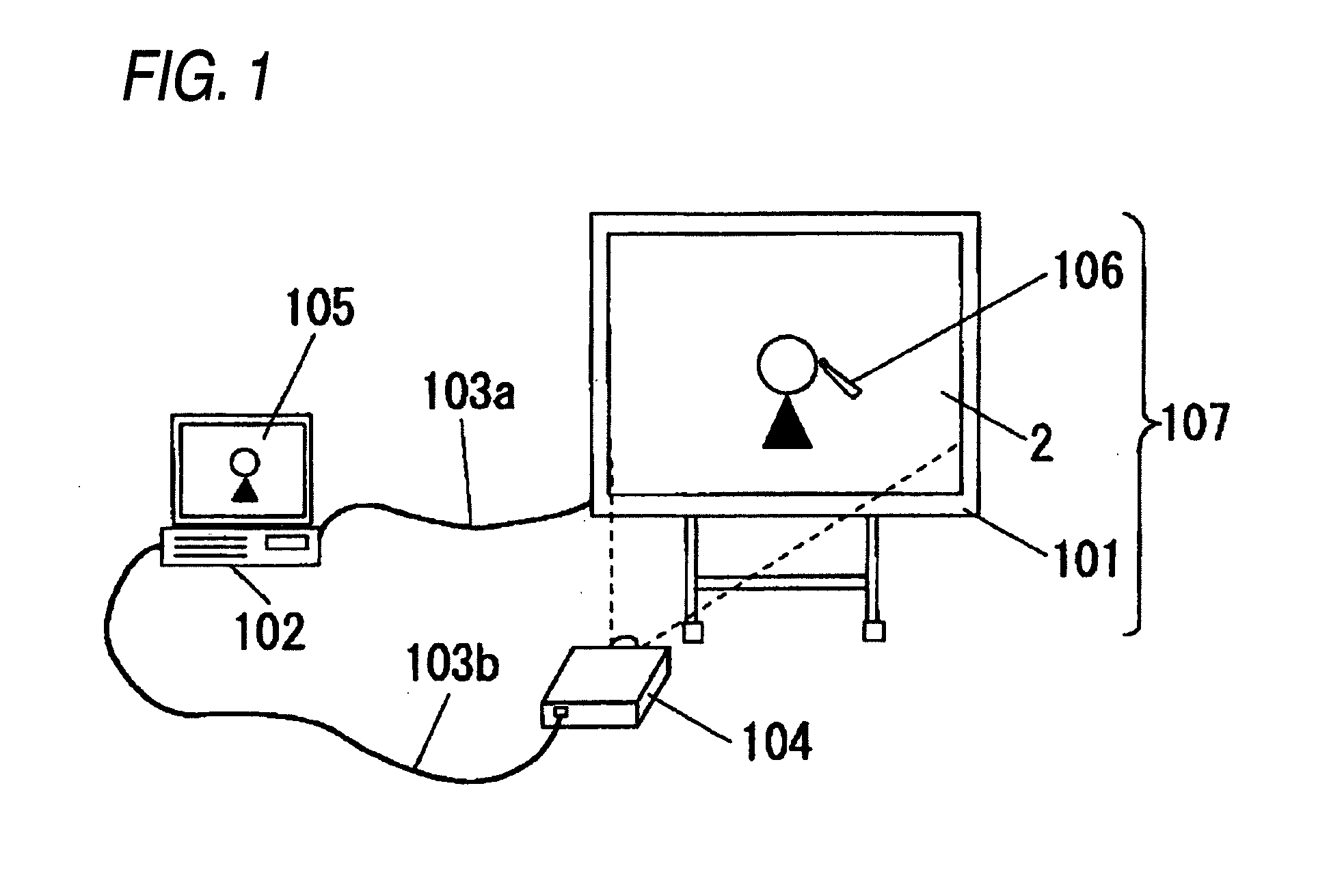
[0051]FIG. 1 is a descriptive view showing an electronic white board system that is an application of a capacitive touch panel of a first embodiment of the present invention. The electronic white board system shown in FIG. 1 is made up of a liquid crystal projector 104 and a detection panel 2 that work as a display unit; a coordinate input device 101; a computer 102 connected to them by way of communications cables 103a and 103b; and an electronic pen 106 used for making a handwritten input to the coordinate input device 101.
[0052]A display surface and a coordinate input surface (a write surface) of the electronic white board 107 are made up of the detection panel 2 and the coordinate input device 101. Display data reserved in the computer 102, such as texts, pictures, figures, and graphics, are delivered to the liquid...
PUM
 Abstract
Description
Claims
Application Information