Improvements in or relating to display systems

a display system and display technology, applied in the field of display systems, can solve the problems of affecting the effect of display, and affecting the perception of users, so as to reduce the effect of hyperstereopsis

Active Publication Date: 2010-11-11
SNAP INC
View PDF28 Cites 108 Cited by
  • Summary
  • Abstract
  • Description
  • Claims
  • Application Information

AI Technical Summary

Benefits of technology

[0010]In this manner, a sensor device is included in a waveguide type display system and can be positioned such that is reduces the hyperstereopsis effect perceived by a user.

Problems solved by technology

Hyperstereopsis is a undesirable effect observed when enhanced imagery of a scene is displayed to a user from sensors which are positioned at a stereo separation that is unnatural as perceived by the user.
However, such solutions are large and heavy when installed on a helmet worn by the user.
Hyperstereopsis causes objects to appear distorted and / or closer to the user.
This effect distorts the user's perception of slope in depth.
Conventional sensors, for example night vision cameras, are typically large in size and heavy.
Therefore, such sensors cannot be mounted at a natural interpupil distance of a user.
To do so would introduce too much mass to the front of the helmet worn by the user and could lead to clashes with a helmet visor and associated mechanisms.
It will be understood that similar problems arise for head mounted displays as the mass of the sensors will be positioned such as to increase the mass on the front of the head of a user.

Method used


Image

  • Improvements in or relating to display systems
  • Improvements in or relating to display systems
  • Improvements in or relating to display systems

Examples


Embodiment Construction

[0022]Exemplary embodiments of the present invention will now be described in more detail, by way of example only, with reference to the accompanying drawings.

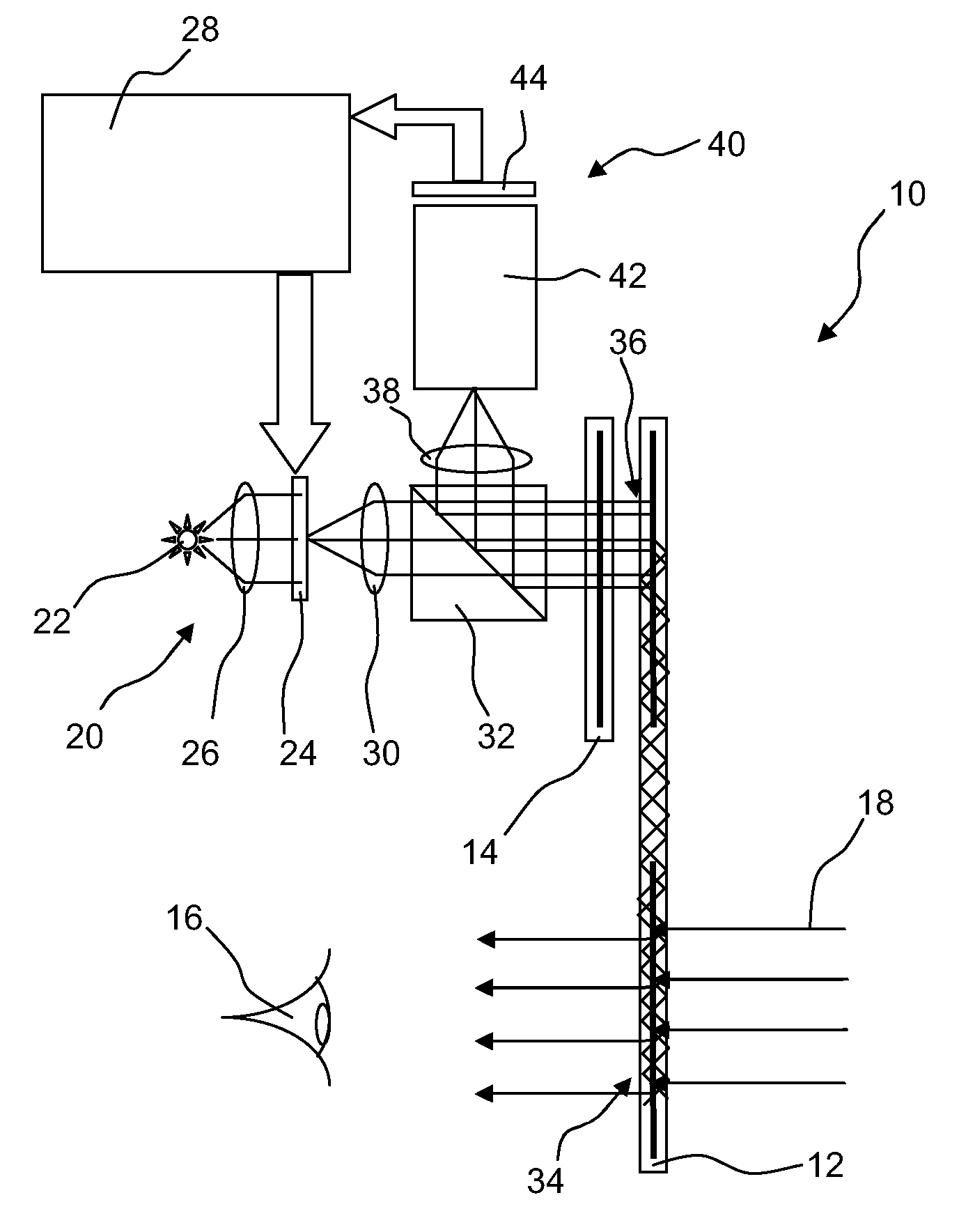
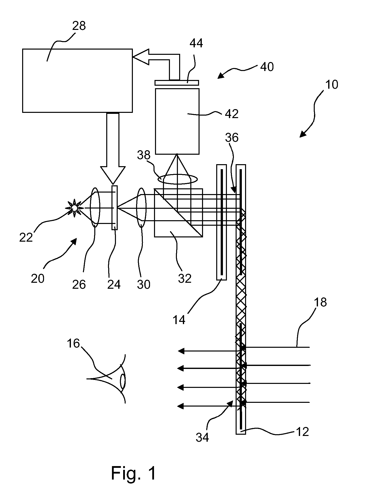
[0023]Referring to FIG. 1, a display system 10 includes a primary waveguide 12 and a coupling waveguide 14 arranged substantially co-planar with one another. The primary waveguide 12 is arranged such that a user 16 can view light from a forward scene 18 through the primary waveguide 12.

[0024]An image source 20, including a light source 22 arranged to illuminate a display device 24 via a collection lens 26, is arranged to generate an image to be displayed to the user 16. Collection lens 26 is arranged to focus light from the light source 22 on to the display device 24. The image generated by the image source 20 is dependent on signals generated by an image processor 28 that is used to drive the display device 24. The display device 24 can be a suitable digital display device that is transmissive to light constituting the image ...


PUM


Abstract

A primary waveguide and a coupling waveguide are arranged so a user can view light from a forward scene through the primary waveguide. An image source generates an image which is diffractively coupled into the primary waveguide and internally reflected to an exit area for diffraction towards the user. Light from the forward looking scene is diffracted into the primary waveguide to be internally reflected and coupled to a image intensifier tube assembly. The image intensifier tube assembly enhances light from the forward looking scene and drives the image source such that an image of the enhanced light is overlaid on light from a forward scene at exit area.

Description

RELATED APPLICATION INFORMATION[0001]This application is a United States National Phase patent application of International Patent Application No. PCT / GB2008 / 050919 which was filed on Oct. 7, 2008, and claims priority to British Patent Application No. 0720386.2, filed on Oct. 18, 2007, and claims priority to European Patent Application No. 07270061.0, filed on Oct. 18, 2007, the disclosures of each of which are incorporated herein by reference.FIELD OF THE INVENTION[0002]This invention relates to a display system, which is particularly, but not exclusively, suitable for use in head mounted or helmet mounted display apparatus.BACKGROUND INFORMATION[0003]Hyperstereopsis is a undesirable effect observed when enhanced imagery of a scene is displayed to a user from sensors which are positioned at a stereo separation that is unnatural as perceived by the user. The extent of the hyperstereopsis effect is dictated by the size of the sensors used and the ability to sensibly mount such sensor...

Claims


Application Information

Patent Timeline
Patent Type & Authority Applications(United States)
IPC IPC(8): G02B27/01
CPCG02B6/00G02B27/0081G02B2027/0138G02B2027/0134G02B27/0172
Inventor SIMMONDS, MICHAEL DAVID
Owner SNAP INC
Why Eureka
Try Eureka