Light receiving circuit and signal processing method

a light receiving circuit and signal processing technology, applied in electromagnetic transmission, instruments, transmission, etc., can solve the problems of increasing the cmrr, affecting the reception performance of two signals, and unable to maintain the reception intensities or phases of two signals, so as to achieve the effect of improving the reception performan

Active Publication Date: 2010-11-11
NEC CORP
View PDF6 Cites 30 Cited by
  • Summary
  • Abstract
  • Description
  • Claims
  • Application Information

AI Technical Summary

Benefits of technology

[0012]According to this invention, a phase difference or a difference in light reception intensity in two signals that occurs before RZ-DPSK signal demodulation is corrected through the adjustment to the levels of the positive and negative phase signals o

Problems solved by technology

In actuality, however, the two signals may not maintain their reception intensities or phases because of an intensity difference or an optical path difference between the two optical signals that is caused before the optical signals are input to the two PDs after having passed through the interferometer and lenses, as well as a difference in conversion efficiency of the PDs.
The difference in reception int

Method used


Image

  • Light receiving circuit and signal processing method
  • Light receiving circuit and signal processing method
  • Light receiving circuit and signal processing method

Examples


first embodiment

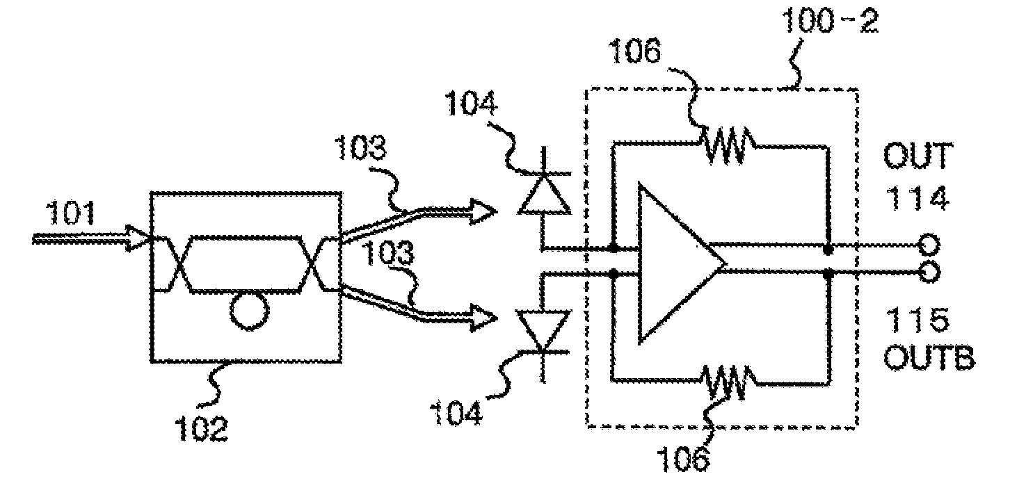
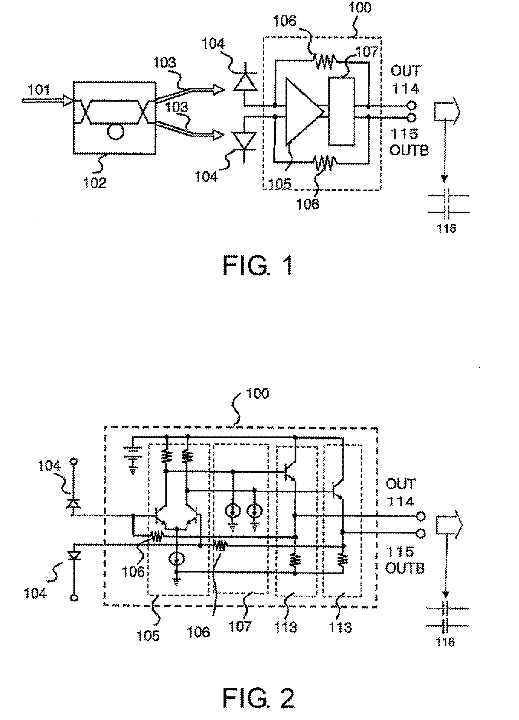
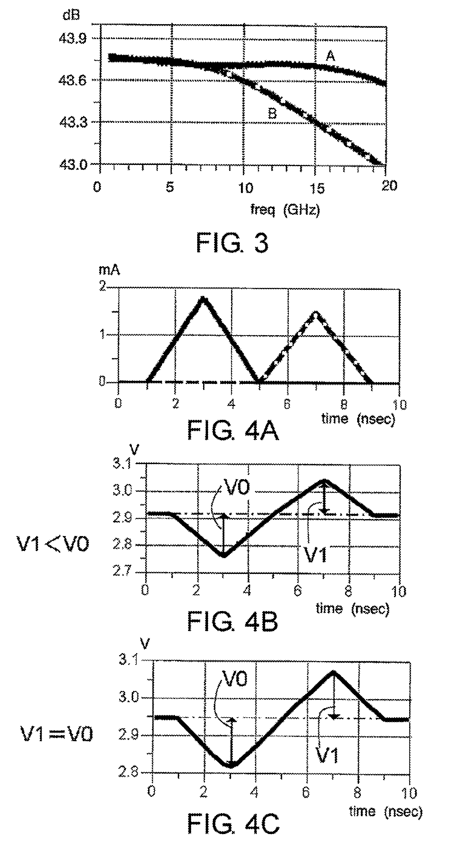
[0032]Referring to FIG. 1 to FIG. 4C, a first embodiment of this invention is described in detail. FIG. 1 is a block diagram of a light receiving circuit according to the first embodiment of this invention. FIG. 2 is a circuit diagram illustrating a circuit configuration example of the light receiving circuit. FIG. 3 illustrates gain dependence on frequency before and after RZ-DPSK demodulation, and FIGS. 4A to 4C illustrate signal waveforms before and after RZ-DPSK demodulation.

[0033]The light receiving circuit illustrated in FIG. 1 includes a 1-bit delay interferometer 102, two photodiodes (PDs) 104 and 104 for receiving two optical signals 103 and 103 corresponding to a phase difference between adjacent bits, respectively, and a differential transimpedance amplifier 100. The transimpedance amplifier 100 includes a differential amplifier 105 for inputting the two optical signals 103 and 103 from the two photodiodes (PDs) 104 and 104, a level adjusting circuit 107, and feedback res...

second embodiment

[0042]Referring to FIG. 5 and FIG. 6A to FIG. 6D, a second embodiment of this invention is described. FIG. 5 illustrates a block diagram of a light receiving circuit for RZ-DPSK signals according to the second embodiment of this invention. FIG. 6A to FIG. 6D illustrate signal waveforms obtained before and after adjustment to DC levels, illustrating effects produced by the light receiving circuit of this invention. The light receiving circuit of this embodiment is realized by adding, at a subsequent stage of the light receiving circuit according to the first embodiment, a main amplifier 108 and a DC level correcting circuit 109 for correcting a DC level difference.

[0043]To be described in detail, the light receiving circuit of FIG. 5 includes the 1-bit delay interferometer 102, the two photodiodes (PDs) 104 and 104, the differential transimpedance amplifier 100, the main amplifier 108, and the DC level correcting circuit 109. The 1-bit delay interferometer 102 inputs the optical sign...

third embodiment

[0050]Referring to FIG. 7, a third embodiment of this invention is described. FIG. 7 illustrates a circuit diagram of a light receiving circuit for RZ-DPSK signals according to the third embodiment. The light receiving circuit of this embodiment is another example of a circuit configuration of a light receiving circuit having the same function as in the light receiving circuit according to the first embodiment.

[0051]The light receiving circuit of FIG. 7 includes the 1-bit delay interferometer 102, the two photodiodes (PDs) 104 and 104 for receiving the two optical signals 103 and 103 corresponding to a phase difference between adjacent bits, the differential transimpedance amplifier 100, and an output amplifier 110. The differential transimpedance amplifier 100 includes the differential amplifier 105 having inputs connected to the two PDs 104 and 104, the two emitter follower circuits 113 and 113 formed of transistors, which are connected to the positive and negative phase outputs o...


PUM


Abstract

A light receiving circuit includes: a 1-bit delay interferometer; two photodiodes; and a demodulating circuit for converting current signals of the photodiodes into voltages to thereby demodulate signals that have been modulated by return-to-zero differential phase shift keying, the demodulating circuit including a differential transimpedance amplifier, in which the differential transimpedance amplifier includes a level adjusting circuit that has a function of adjusting levels of a positive phase signal and a negative phase signal of two feedback closed loops.

Description

TECHNICAL FIELD[0001]This invention relates to a light receiving circuit, and more particularly, to a light receiving circuit for receiving and demodulating an optical signal that has been subjected to return-to-zero (RZ) differential phase shift keying (DPSK) or return-to-zero (RZ) differential quadrature phase shift keying (DQPSK) as modulation coding.BACKGROUND ART[0002]In a long-distance optical transmission system, large-capacity information transmission is economically realized by applying the wavelength division multiplexing (WDM) transmission technology, in which optical signals with a plurality of wavelengths are transmitted white being multiplexed in one optical fiber. Regarding a WDM transmission device, an increase in transmission rate per wavelength is now being studied for reducing the device cost. At present, a transmission rate of 10 Gbit / s per wavelength is available for practical use, and further, transmission at 40 Gbit / s is now being studied.[0003]A major challen...

Claims


Application Information

Patent Timeline
IPC IPC(8): H04B10/06H03F3/08H04B10/67H04B10/69
CPCH01L31/02019H04B10/6933H04B10/677H03F3/08
Inventor SUZUKI, YASUYUKI
Owner NEC CORP
Why Eureka
Try Eureka