Transcranial magnetic stimulation field shaping

a transcranial magnetic stimulation and field shaping technology, applied in magnetotherapy, magnetotherapy using coils/electromagnets, magnetotherapy, etc., can solve the problems of pain and discomfort of patients, inability to achieve deep brain modulation, undetectable side effects such as seizures, etc., to reduce current (power), enhance the focusing of the emitted field, and reduce the power applied

Active Publication Date: 2010-11-11
BRAINSWAY
View PDF99 Cites 55 Cited by
  • Summary
  • Abstract
  • Description
  • Claims
  • Application Information

AI Technical Summary

Benefits of technology

[0020]Reducing the current (power) applied to the secondary TMS electromagnets (which may be referred to as ‘side coils’) compared to the primary TMS electromagnet(s) may enhance focusing of the emitted field. Reducing the power applied to the secondary TMS electromagnets may also reduce or prevent pain or discomfort experienced by a subject undergoing TMS. Reducing the power applied to the secondary TMS electromagnets may also reduce the stimulation of non-target tissue regions, including more cortical regions (e.g., regions intermediate to the target), and sensory nerves of the orbit and sinuses. For example, PCT / US2008 / 073751, previously incorporated by reference, describes one such system. In variations in which a “front” secondary TMS electromagnet is used, such as a secondary TMS electromagnet that is positioned over the subjects facial region (e.g., forehead, eyes, nose, etc.) the patient, the power applied may be less than the other secondary TMS electromagnets.

Problems solved by technology

For example, the cingulate gyms, the insula and other subcortical structures are generally not directly accessible for modulation traditional TMS without causing overstimulation of non-target (e.g., more superficially located regions) which may lead to pain and discomfort for the patient).
Deep brain modulation cannot be accomplished by simply turning up the power of the stimulating electromagnet, because the intervening tissue, including superficial cortex, will be over-stimulated, causing undesired side effects such as seizures.

Method used


Image

  • Transcranial magnetic stimulation field shaping
  • Transcranial magnetic stimulation field shaping
  • Transcranial magnetic stimulation field shaping

Examples


examples

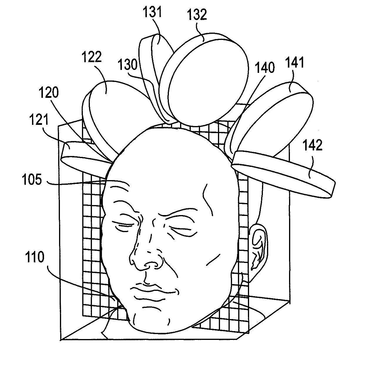
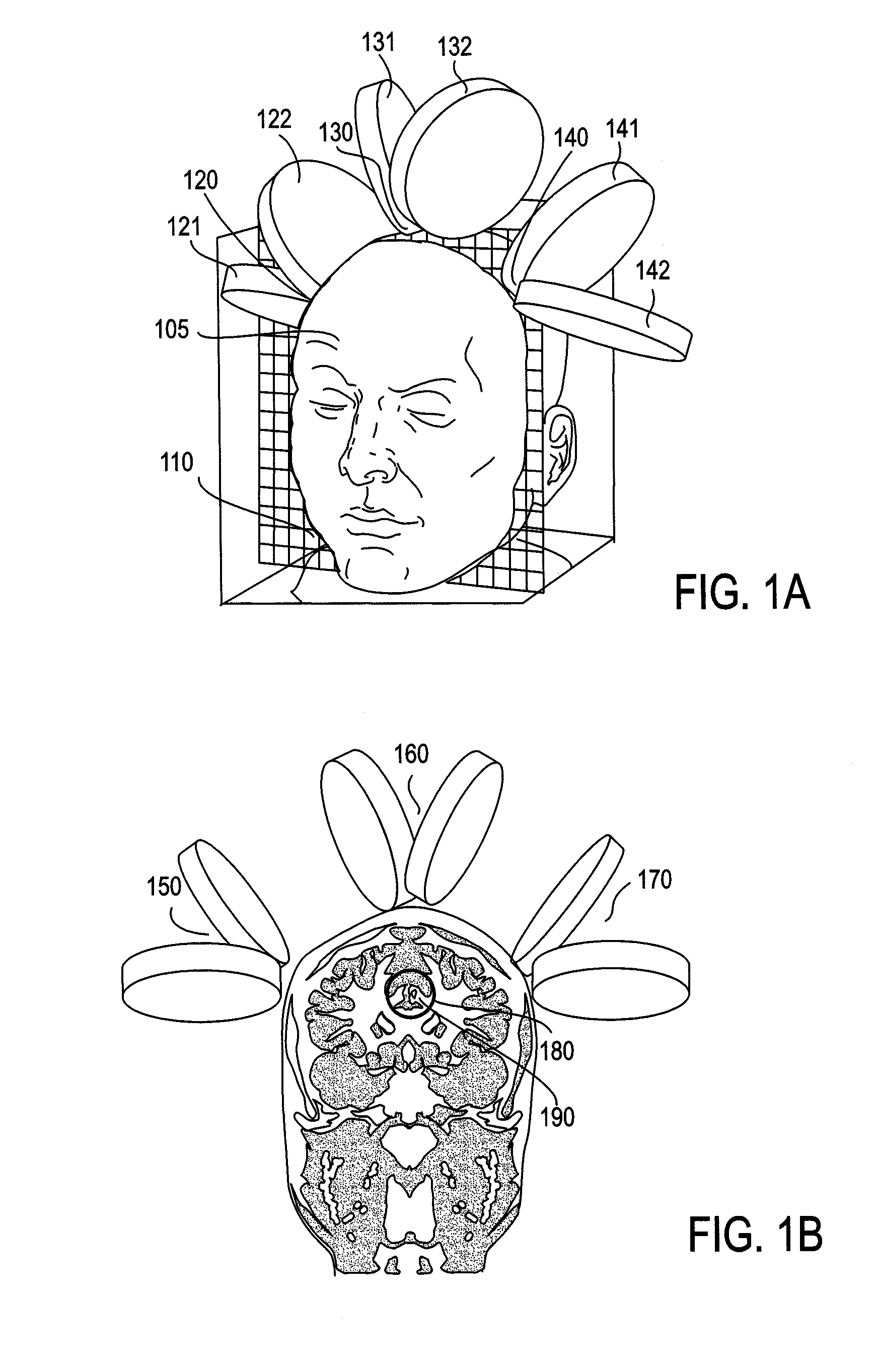
[0055]FIG. 1A shows one example of an array of three TMS electromagnet stimulator coils arranged around a patient's head. In this variation (which may be referred to as a triad array), the patients head 105 is shown transected by plane 110, which corresponds to the cross-section shown in FIG. 1B. The modified image shown is based in part on image data from Voxel-Man 3D Navigator. In FIGS. 1A and 1B, the V-shaped double coil 120 (also designated as coil A) is composed of circular coils 121 and 122, and bent at the center where the return path of the current in both coils is in the same direction. Similarly, V-shaped double coil 130 (also designated as coil B) is composed of circular coils 131 and 132 joined at a bent center, and V-shaped double coil 140 (also designated as coil C) is composed of circular coils 141 and 142, joined at a bent center. As described above, any of these coils may also be of other designs, for example flat double coils, flat-bottomed (swept-wing) V coils, or...


PUM


Abstract

Described herein are Transcranial Magnetic Simulation (TMS) systems and methods of using them for emitting focused, or shaped, magnetic fields for TMS. In particular, described herein are arrays of TMS electromagnets comprising at least one primary (e.g., central) TMS electromagnet and a plurality of secondary (e.g., lateral or surrounding) TMS electromagnets. The secondary TMS electromagnets are arranged around the primary TMS electromagnet(s), and are typically configured to be synchronously fired with the primary TMS electromagnets. Secondary TMS electromagnets may be fired at a fraction of the power used to energize the primary TMS electromagnet to shape the resulting magnetic field. The secondary TMS electromagnets may be stimulated at opposite polarity to the primary TMS electromagnet(s). Focusing in this manner may prevent or reduce stimulation of adjacent non-target brain regions.

Description

CROSS REFERENCE TO RELATED APPLICATIONS[0001]This patent application claims priority as a continuation-in-part of U.S. patent application Ser. No. 12 / 670,938, filed on Jan. 27, 2010, titled “FIRING PATTERNS FOR DEEP BRAIN TRANSCRANIAL MAGNETIC STIMULATION”, which claims priority to PCT Patent Application No. PCT / US2008 / 073751, filed on Aug. 20, 2008, which claims priority to U.S. Provisional Patent Application No. 60 / 956,920, filed on Aug. 20, 2007, U.S. Provisional Patent Application No. 60 / 970,958, filed on Sep. 9, 2007, and U.S. Provisional Patent Application No. 61 / 077,488, filed on Jul. 2, 2008.[0002]This patent application also claims priority as a continuation-in-part of U.S. patent application Ser. No. 12 / 701,395, filed on Feb. 5, 2010, titled “CONTROL AND COORDINATION OF TRANSCRANIAL MAGNETIC STIMULATION ELECTROMAGNETS FOR MODULATION OF DEEP BRAIN TARGETS”, which claims priority as a continuation-in-part to PCT Patent Application No. PCT / US2008 / 075575, filed on Sep. 8, 2008...

Claims


Application Information

Patent Timeline
Patent Type & Authority Applications(United States)
IPC IPC(8): A61N2/04
CPCA61N2/02A61N2/006
Inventor SCHNEIDER, M. BRETMISHELEVICH, DAVID J.
Owner BRAINSWAY
Why Eureka
Try Eureka