Manufacturing method of golf club head

a manufacturing method and golf club head technology, applied in golf clubs, manufacturing tools, shaping tools, etc., can solve the problems of excessive sharpness, excessive sharpness, disadvantageous sharpness of golf balls, etc., and achieve the effect of suppressing fluctuation in the shape of the face lin

Inactive Publication Date: 2010-11-18
SUMITOMO RUBBER IND LTD
View PDF8 Cites 3 Cited by
  • Summary
  • Abstract
  • Description
  • Claims
  • Application Information

AI Technical Summary

Benefits of technology

[0009]It is an object of the present invention to provide a manufacturing m...

Problems solved by technology

In the case of the cutting processing, an excessively sharp edge is formed.
The excessively sharp edge disadvantageously damages a golf ball.
The e...

Method used


Image

  • Manufacturing method of golf club head
  • Manufacturing method of golf club head
  • Manufacturing method of golf club head

Examples


example 1

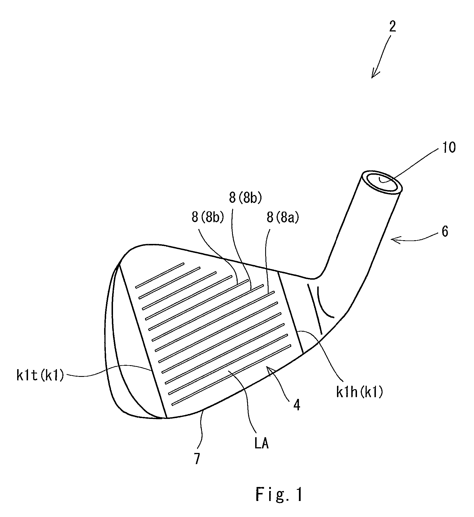
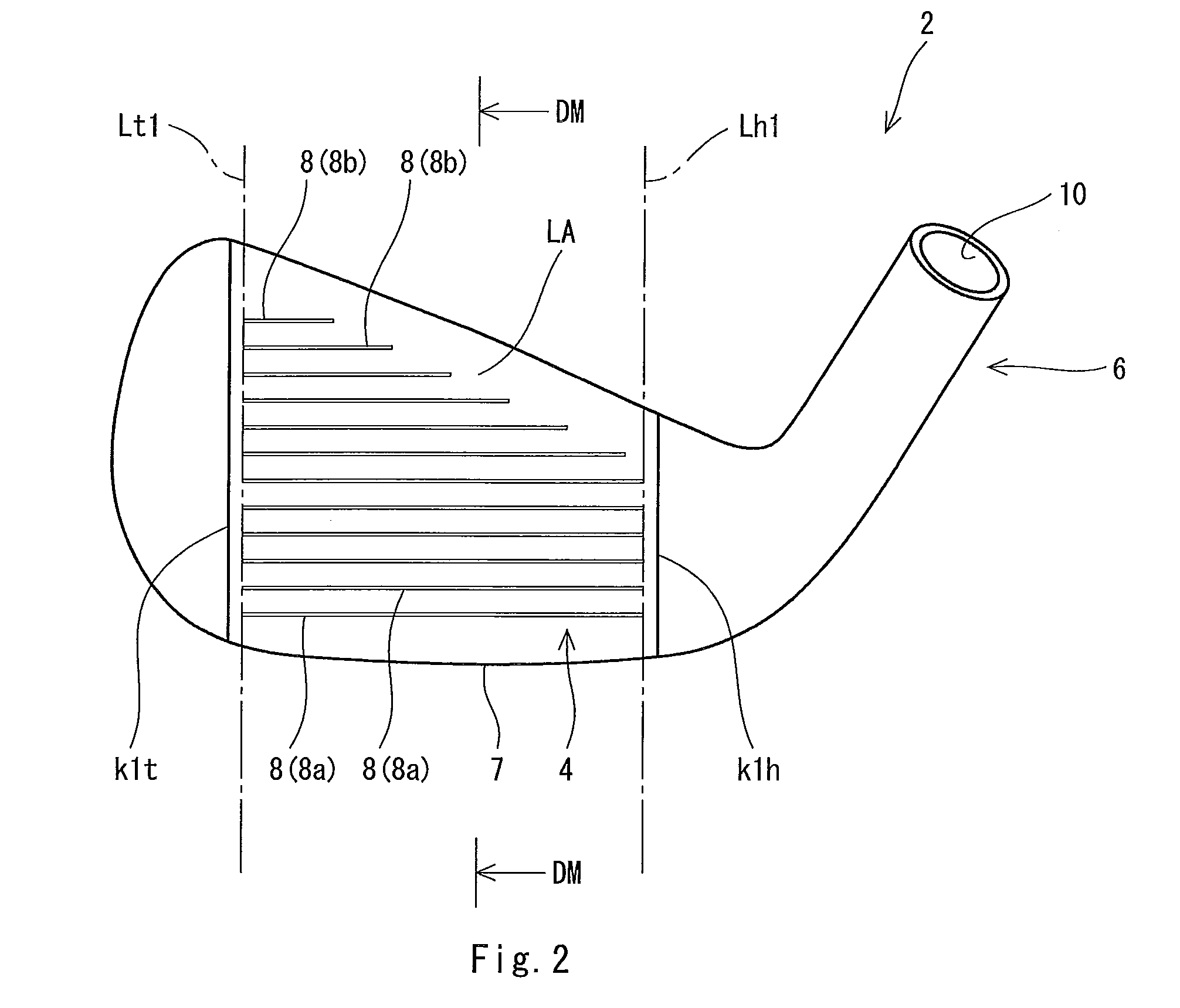
[0139]A face plate used for an iron type golf club head was prepared. The face plate has a plate shape. The face plate is made of a titanium alloy. The face plate is used by being combined with a head body having a face part having an opening. Specifically, the face plate is fitted into the opening to produce a golf club head.

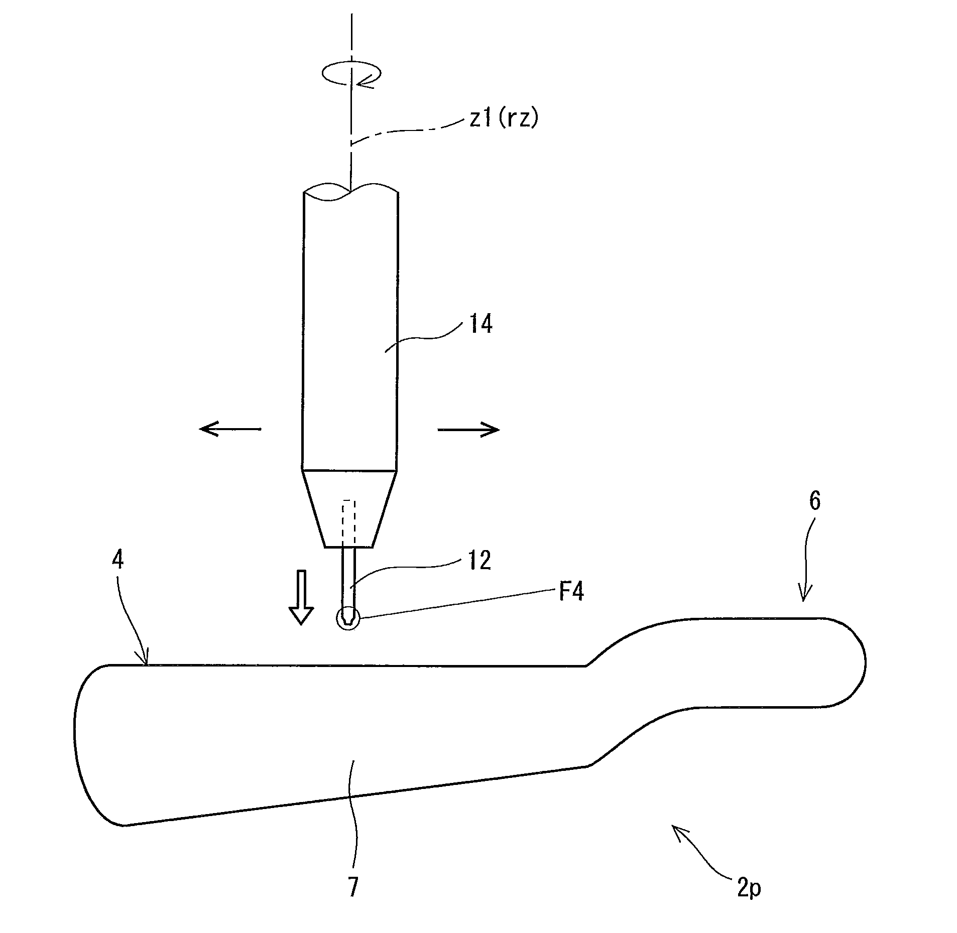
[0140]Cut processing of a face line was carried out in the same manner as in the head 2 except that the face plate was used in place of the head 2p of FIG. 3. The shape of a cutter was set as shown in FIGS. 4 and 5. A curvature radius R1 of a recessed curved surface of the cutter was 0.24 mm (constant). An cutter angle θg1 and a groove angle θg2 were set to 20 degrees. A width Wp of an upper side plane part was set to 0.5 mm. A position in the vertical direction of a cutter 12 was set so that a second straight part c5 is brought into contact with a land area LA. More specifically, the position in the vertical direction (a position of a central axis line z1 dire...

example 2

[0141]A face line according to example 2 was obtained in the same manner as in the example 1 except that a curvature radius R1 of a cutter was set to 0.30 (mm) and the other specifications were set as shown in Table 1. The specification and the evaluation result of the example 2 are shown in the following Table 1.


PUM

PropertyMeasurementUnit
Angleaaaaaaaaaa
Angleaaaaaaaaaa
Radiusaaaaaaaaaa

Abstract

A manufacturing method of the present invention includes the steps of: preparing a pre-line forming member having no face line; and cutting the pre-line forming member using a cutter 12 to form the face line on the pre-line forming member. The cutter 8 has a tip part having a cutting surface. The cutting surface has a recessed curved surface c4. An edge of the face line 8 is cut by the recessed curved surface c4. Preferably, the step of cutting is carried out by axial rotation of the cutter 8. Preferably, the cutting surface has a plane part c5 formed on an upper side of the recessed curved surface c4. Preferably, the upper side plane part c5 is perpendicular to a rotation axis rz of the cutter 12. Preferably, the cutting surface has a conical surface Fc formed on a lower side of the recessed curved surface c4.

Description

[0001]This application claims priority on Patent Application No. 2009-116171 filed in JAPAN on May 13, 2009, the entire contents of which are hereby incorporated by reference.BACKGROUND OF THE INVENTION[0002]1. Field of the Invention[0003]The present invention relates to a manufacturing method of a golf club head having face lines.[0004]2. Description of the Related Art[0005]Face lines are formed on many golf club heads. The face lines can contribute to an increase in the backspin rate (backspin amount) of a hitting ball. The face lines can suppress fluctuation in the backspin rate.[0006]As a forming method of the face lines, press processing and cut processing (machining) have been known. Japanese Patent Application Laid-Open No. 2003-199851 (US2003 / 126734A1) discloses face lines formed by the press processing. Japanese Patent Application Laid-Open No. 2008-206984 (US2007 / 0149312A1) discloses face lines formed by the cut processing (machining). Japanese Patent Application Laid-Open...

Claims


Application Information

Patent Timeline
IPC IPC(8): B23P15/00A63B53/04A63B102/32
CPCA63B53/04A63B53/0487A63B2053/0408A63B2053/0445A63B2209/00A63B2209/02Y10T29/49995B23C5/10B23C2200/203B23C2200/205B23C2265/08A63B53/047Y10T29/49996B23C3/30Y10T83/0605Y10T83/0304Y10T83/05A63B53/0445A63B53/0408
Inventor NAKANO, TAKASHI
Owner SUMITOMO RUBBER IND LTD
Why Eureka
Try Eureka