Printing method by offset printing press and offset printing press

Inactive Publication Date: 2010-11-18
MITSUBISHI HEAVY IND PRINTING & PACKAGING MACHINERY
View PDF0 Cites 6 Cited by
  • Summary
  • Abstract
  • Description
  • Claims
  • Application Information

AI Technical Summary

Benefits of technology

[0036]With the printing method by an offset printing press and the offset printing press of the present invention, the substrate treatment agent is supplied to the printing face of printing paper such that a porous layer having a great number of holes with a smaller diameter than that the pigment contained in the printing ink is formed from solid fine particles and a binder component contained in the substrate treatment agent and then printing is carried out. Therefore, although the solvent contained in the printing ink transferred on the printing face is infiltrated into the printing paper through the small diameter holes of the porous layer, the pigment contained in the printing ink is blocked by the porous layer and is retained on the printing face. By the infiltration of the solvent into the printing paper through the small diameter holes of the porous layer, drying of the printing ink on the printing face is accelerated while the pigment contained in the ink is retained on the printing face. Consequently, the phenomenon (drydown) that the printing density decreases is suppressed and a sufficient color reproduction range is secured. As a result, particularly color printing can be carried out with high color reproducibility and with a higher definition.

Problems solved by technology

Incidentally, in case of printing paper wherein clearances of paper fibers are comparatively great such as paper for newspaper, as described above, it cannot be avoided that a phenomenon (drydown) occurs that ink (particularly, pigment) on the paper face sinks into clearances of paper fibers during several hours after printing and the printing density drops.
Also by this drydown, the pigment density per a unit volume in an ink layer drops, and therefore, this phenomenon makes a cause of narrowing of the color reproduction range.

Method used


Image

  • Printing method by offset printing press and offset printing press
  • Printing method by offset printing press and offset printing press
  • Printing method by offset printing press and offset printing press

Examples


first embodiment

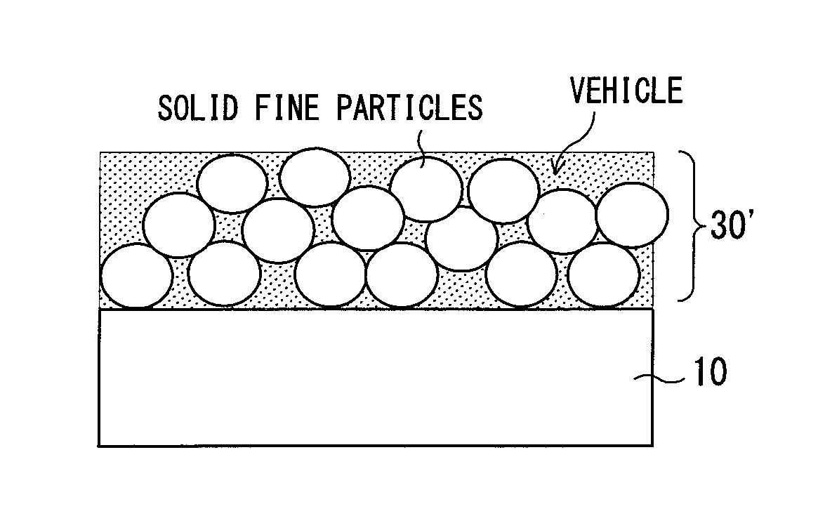
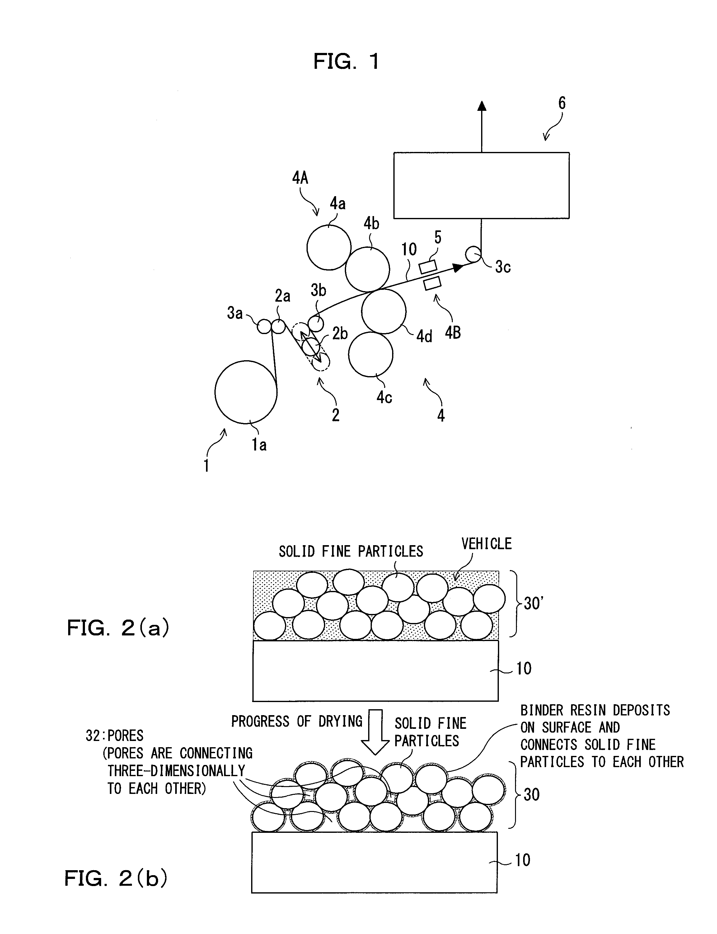
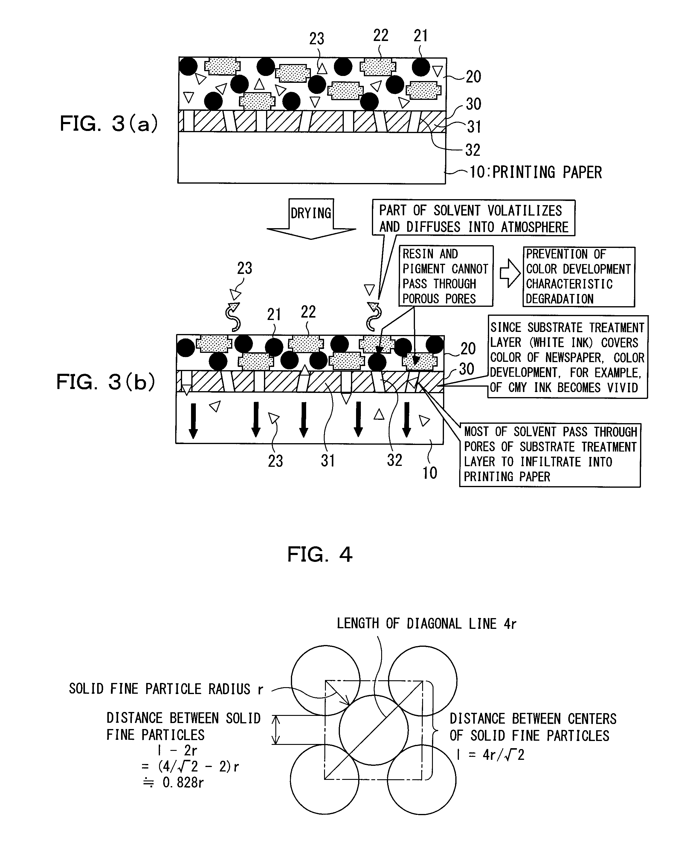
[0079]First, a first embodiment of the present invention is described. FIGS. 1 to 10 illustrate the first embodiment of the present invention, and wherein FIG. 1 is an explanatory view showing a configuration of essential part of an offset printing press of the present embodiment and FIGS. 2(a) and 2(b) are conceptual views illustrating a forming process of a porous layer with substrate treatment agent supplied to the printing face. FIGS. 3(a) and (b) are conceptual views regarding drying of moisture supplied to the reverse face and the substrate treatment agent supplied to the printing face and FIG. 4 is a schematic structure view illustrating a distance between solid fine particles contained in the substrate treatment agent. Further, FIG. 5 is a front elevational view showing a printing face of the paper for newspaper and FIG. 6 is a flow chart illustrating a printing method by the offset printing press. Further, FIGS. 7 to 10 are views illustrating experiments according to the pr...

second embodiment

[0151]Now, a second embodiment of the present invention is described. FIG. 11 is an explanatory view showing a configuration of essential part of an offset printing press in the second embodiment of the present invention. In FIG. 11, like elements to those in FIG. 1 are denoted by like reference characters and description of the like elements is partly omitted.

[0152]While the first embodiment is configured such that the substrate treatment agent supplying apparatus (substrate treatment agent supplying section 4A and drying processing section 4B) 4 is added to an existing newspaper rotary press, the present embodiment is configured such that the substrate treatment agent supplying apparatus 4 is incorporated originally in a newspaper rotary press. In particular, as shown in FIG. 11, the substrate treatment agent supplying apparatus 4 is mounted on the upstream side of the printing section 6 including printing units 6a and 6b and so forth in a juxtaposed relationship with the printing...

third embodiment

[0155]Now, a third embodiment of the present invention is described. FIG. 12 is an explanatory view showing a configuration of essential part of an offset printing press in the third embodiment of the present invention. In FIG. 12, like elements to those in FIG. 1 are denoted by like reference characters, and description of the like elements is partly omitted. Also in the present embodiment, white pigment is used as the solid fine particle of the substrate treatment agent as an example.

[0156]In the present embodiment, while the substrate treatment agent supplying apparatus 4 itself is same as those in the first and second embodiments, a portion of the printing press on the upstream side with respect to the substrate treatment agent supplying apparatus 4 is different from those in the first and second embodiments.

[0157]In particular, while the dancer roller is provided as an apparatus for varying the web-path length in the first and second embodiments, in the present embodiment, the ...


PUM

PropertyMeasurementUnit
Particle sizeaaaaaaaaaa
Diameteraaaaaaaaaa
Weight ratioaaaaaaaaaa

Abstract

The invention relates to a printing method by an offset printing press and an offset printing press by which a substrate process is carried out for low-whiteness printing paper such as paper for newspaper with aqueous substrate treatment agent so that the print quality can be improved. In the invention, in order to suppress occurrence of a curl of printing paper, substrate treatment agent containing solid fine particles and a binder component is supplied to a printing face of printing paper, and the substrate treatment agent is dried to form a porous layer having a great number of holes having a smaller diameter than that of pigment contained in printing ink from the solid fine particles and the binder resin. Then, offset printing is carried out on the printing paper.

Description

CROSS-REFERENCE TO RELATED APPLICATIONS[0001]The present application is based on International Application No. PCT / JP2008 / 060664, filed on Jun. 11, 2008, which in turn corresponds to Japanese Application No. 2007-153859, filed on Jun. 11, 2007, and priority is hereby claimed under 35 USC §119 based on these applications. Each of these applications are hereby incorporated by reference in their entirety into the present application.TECHNICAL FIELD[0002]The present invention relates to a printing method by an offset printing press and an offset printing press suitable for use with a newspaper rotary press and printing by a newspaper rotary press.BACKGROUND ART[0003]In recent years, the print quality of a picture of a color photograph or the like has enhanced drastically. Not only enhancement of a printing technique and enhancement of the quality of printing ink but also enhancement of the quality of printing paper contribute much to the enhancement of the print quality. Conversely spea...

Claims


Application Information

Patent Timeline
IPC IPC(8): B41F7/02
CPCB41F23/02B41M1/06B41M5/0011D21H19/38B41M5/5218B41M2205/12B41M5/52
Inventor SUDA, YASUHARUTABUCHI, MITSURUOMAE, FUMIKONISHIYAMA, KOJITAKAHASHI, RYOTAUENO, YOSHIAKI
Owner MITSUBISHI HEAVY IND PRINTING & PACKAGING MACHINERY
Why Eureka
Try Eureka