Fuel conservation device

a fuel conservation and fuel technology, applied in the field of combustion engines, can solve the problems of reducing fuel efficiency and increasing emissions, complex devices, and requiring significant disassembly of vehicles, and achieve the effect of increasing the evaporation rate of fuel during combustion

Active Publication Date: 2010-11-18
FERTIG ANDREW L
View PDF29 Cites 10 Cited by
  • Summary
  • Abstract
  • Description
  • Claims
  • Application Information

AI Technical Summary

Benefits of technology

[0008]In light of the foregoing, it is a first aspect of the present invention to provide a fuel conservation device for a combustion engine maintaining a fuel line and an exhaust, said device comprising a heat-exchanging tube having an inlet and an outlet, wherein said inlet and outlet of said heating tube are adapted to be coupled inline with the fuel line; a hollow heating coil disposed about said heat...

Problems solved by technology

Because of the relatively low temperature of the fuel that is delivered to the engine, it is incompletely burned during combustion, resulting in reduced fuel efficiency and increased emissions.
However, such devices are complex and require significant disassembly of the vehicle in order to install.
In addition...

Method used


Image

  • Fuel conservation device
  • Fuel conservation device
  • Fuel conservation device

Examples


Embodiment Construction

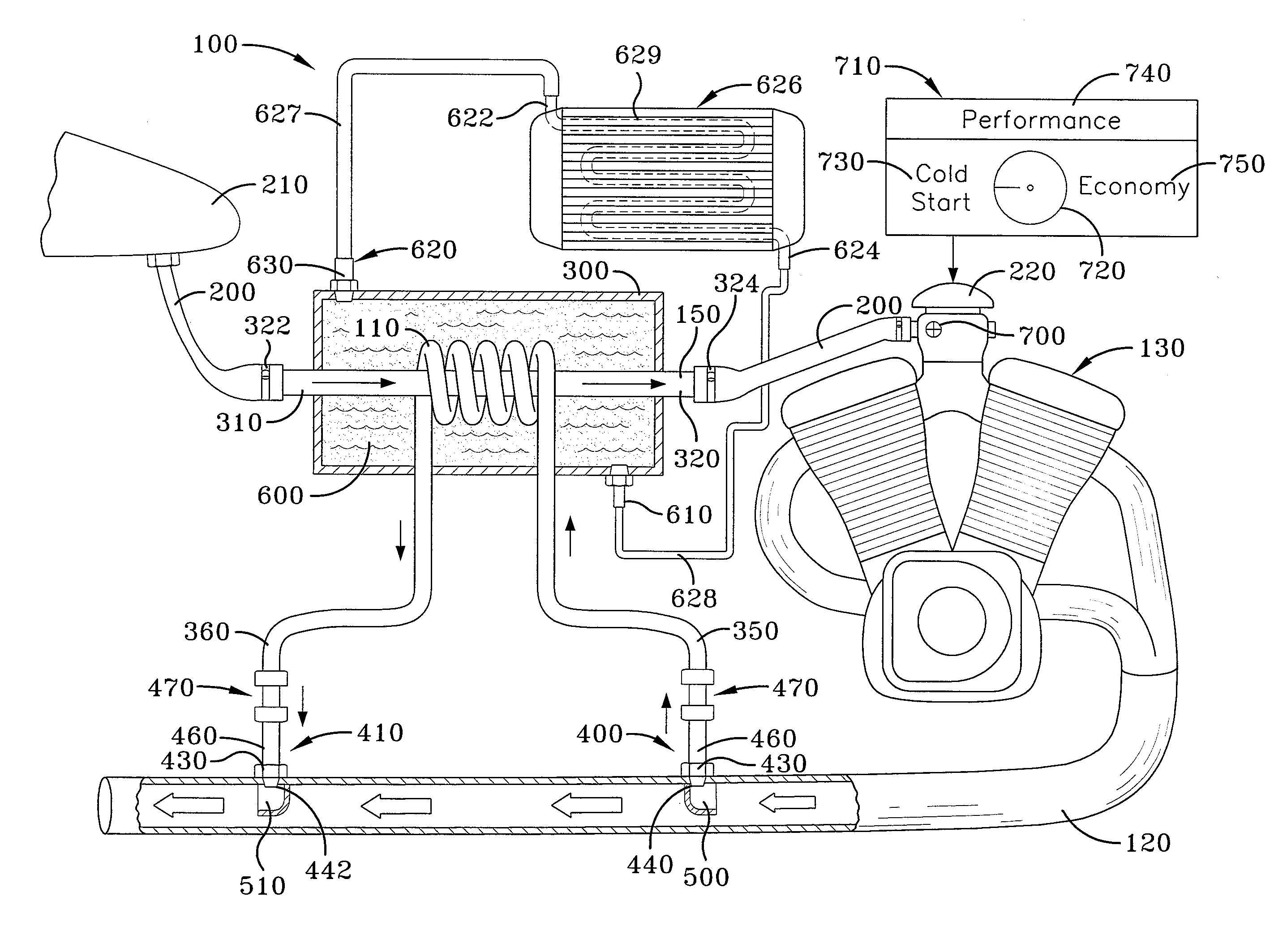
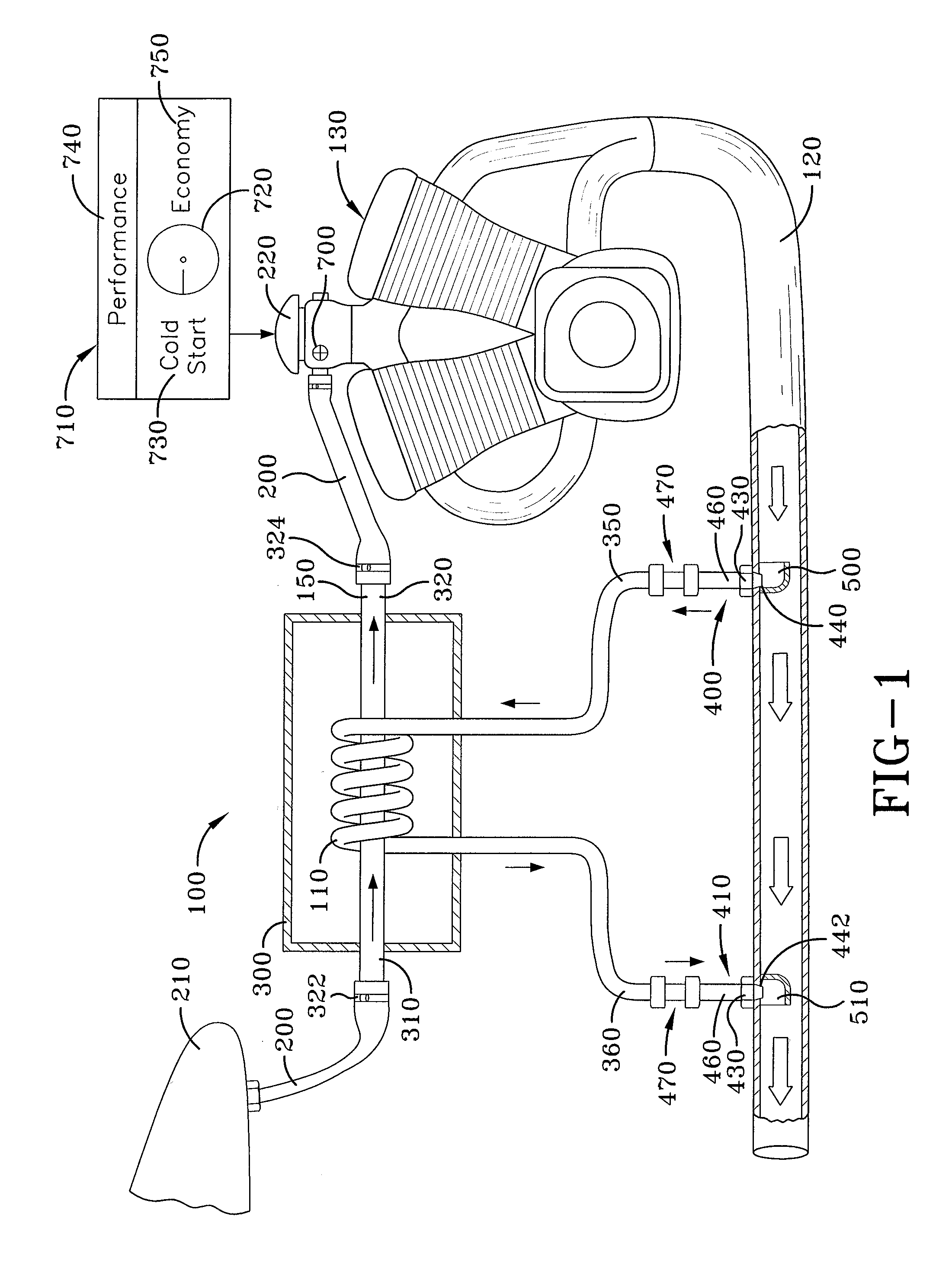
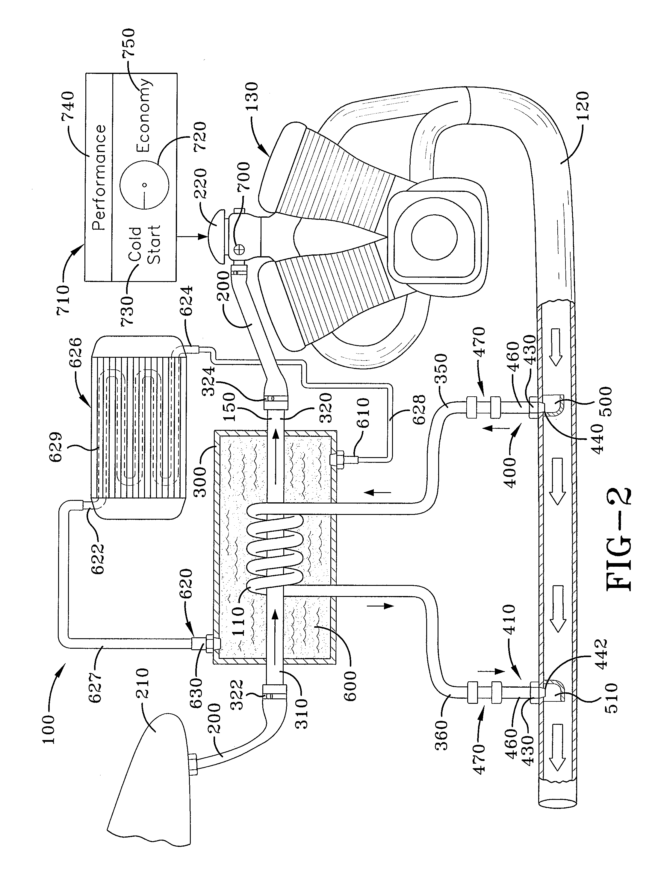
[0018]A fuel conservation device is generally referred to by the numeral 100, as shown in FIG. 1 of the drawings. The fuel conservation device 100 includes a heating coil 110 that receives hot exhaust fumes from an exhaust 120 of a combustion engine 130, such as that maintained by a motorcycle or an automobile for example. Passing through the heating coil 110 is a heat-exchanging tube 150, which is installed inline with a fuel line 200 that supplies petroleum-based fuel, such as gasoline, from a fuel tank 210 to a fuel management device 220, such as a carburetor / electronic fuel injection (EFI) system, which is maintained by the engine 130. Thus, as the fuel moves through the heat-exchanging tube 150, it is heated by the coil 110 to a temperature that approaches, but is just below, the boiling point of the fuel. The increased temperature allows the fuel to evaporate at an increased rate, such that combustion of the fuel delivered to the engine 130 by the carburetor / EFI system 220...


PUM


Abstract

A fuel conservation device for a combustion engine includes a heat-exchanging tube disposed through a heating coil that is contained within a housing containing coolant. The heat-exchanging tube is adapted to be coupled inline with a fuel line used to supply fuel from a gas tank to a fuel management device, such as a carburetor provided by the engine. In addition, the heating coil is configured to be coupled to an exhaust pipe coupled to the engine, so as to be heated by the hot exhaust gases generated as it operates. A radiator fluidly coupled to the housing cools the coolant, so that the fuel passing through the fuel line is maintained at a temperature just below the boiling point of the fuel.

Description

CROSS-REFERENCE TO RELATED APPLICATION[0001]This application claims the benefit of U.S. Provisional Application No. 61 / 179,080 filed May 18, 2009, the specification of which is incorporated herein by reference.TECHNICAL FIELD[0002]Generally, the present invention relates to combustion engines. In particular, the present invention relates to devices used to heat fuel supplied to combustion engines.[0003]More particularly, the present invention relates to a fuel conservation device that utilizes heated exhaust gases from a combustion engine to heat the fuel supplied thereto, in order to increase the efficiency at which the fuel is utilized.BACKGROUND ART[0004]Combustion engines operate using petroleum-based fuels that are combusted to generate mechanical power, such as that used to propel a vehicle. Thus, fuel is typically delivered from a fuel tank to either a carburetor or to fuel injectors that modulate the amount of fuel that is to be delivered to the combustion chambers of the en...

Claims


Application Information

Patent Timeline
IPC IPC(8): F02G5/00
CPCY02T10/126F02M31/16Y02T10/12
Inventor FERTIG, ANDREW L.
Owner FERTIG ANDREW L
Why Eureka
Try Eureka