Engine compression release method and apparatus

a technology of engine compression and release method, which is applied in the direction of machines/engines, valve arrangements, output power, etc., can solve the problems of large and more expensive batteries and motors than are required for less frequent use, and place unacceptably high stresses on valve gears

Inactive Publication Date: 2014-04-10
MEACHAM G B KIRBY
View PDF7 Cites 5 Cited by
  • Summary
  • Abstract
  • Description
  • Claims
  • Application Information

AI Technical Summary

Problems solved by technology

This repetitive cranking, however, places high torque and energy demands on the starting system, typically a battery powered electric motor, leading to larger and more costly batteries and motors than are required for less frequent use.

Method used


Image

  • Engine compression release method and apparatus
  • Engine compression release method and apparatus
  • Engine compression release method and apparatus

Examples


Embodiment Construction

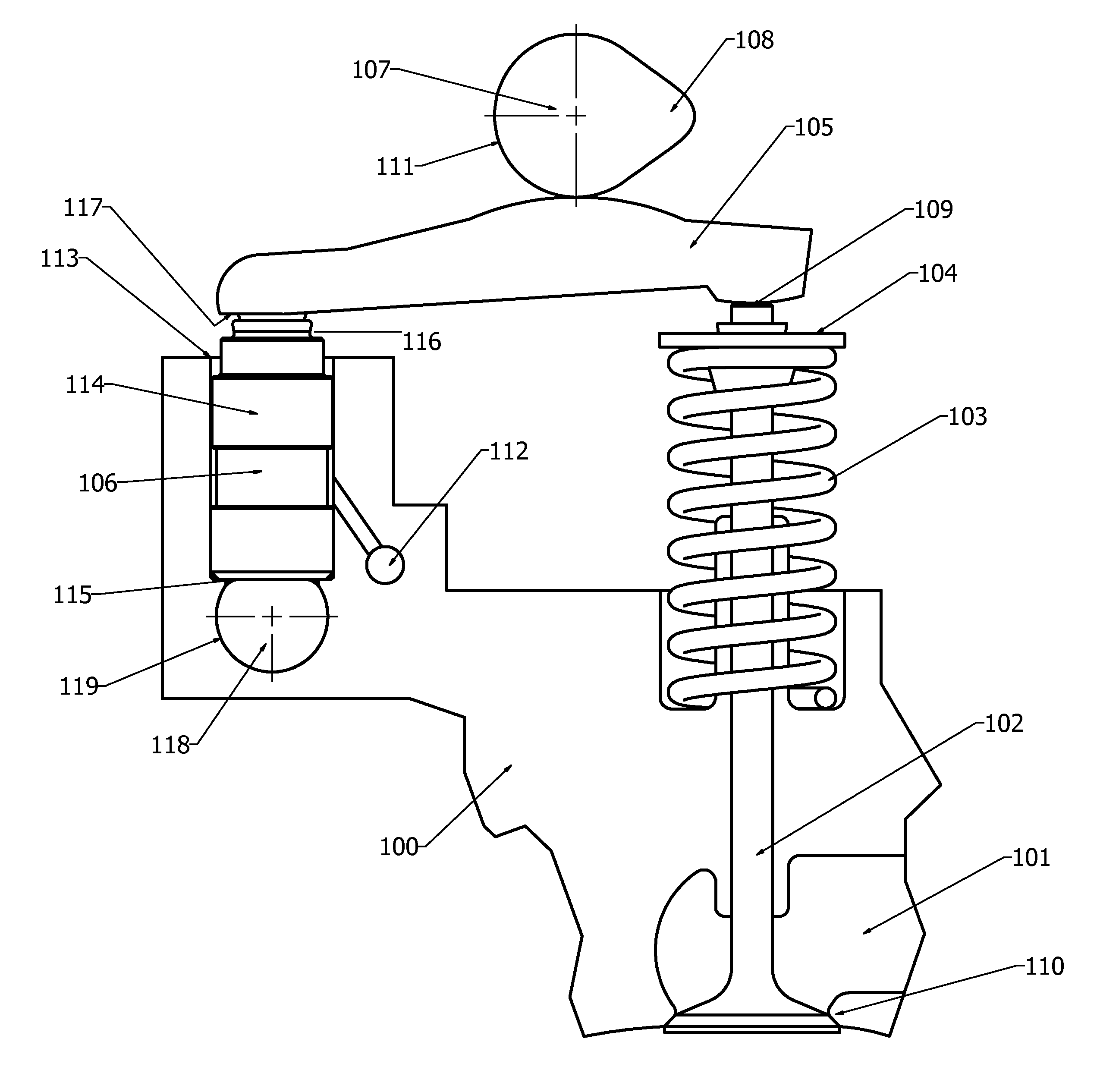
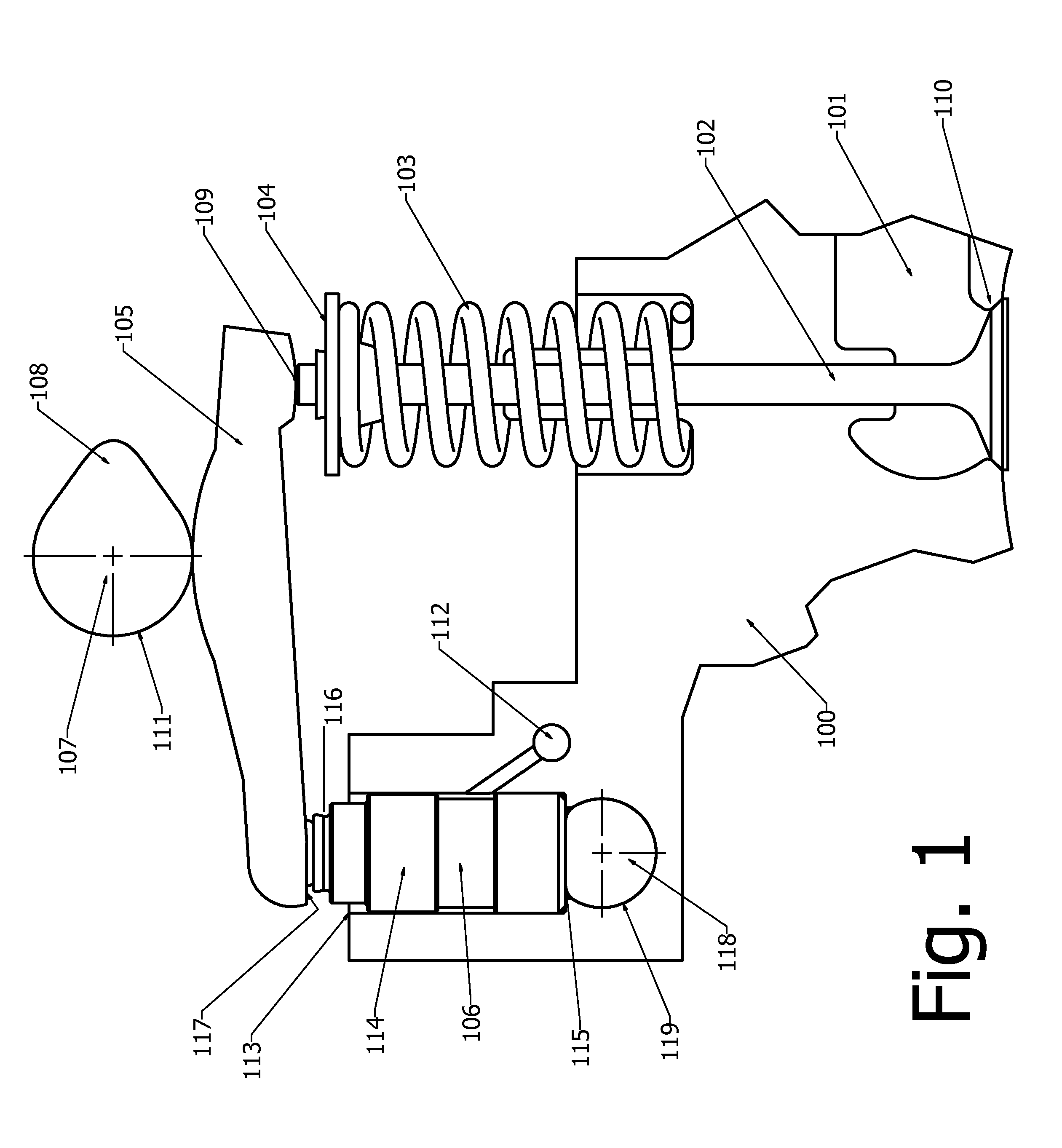
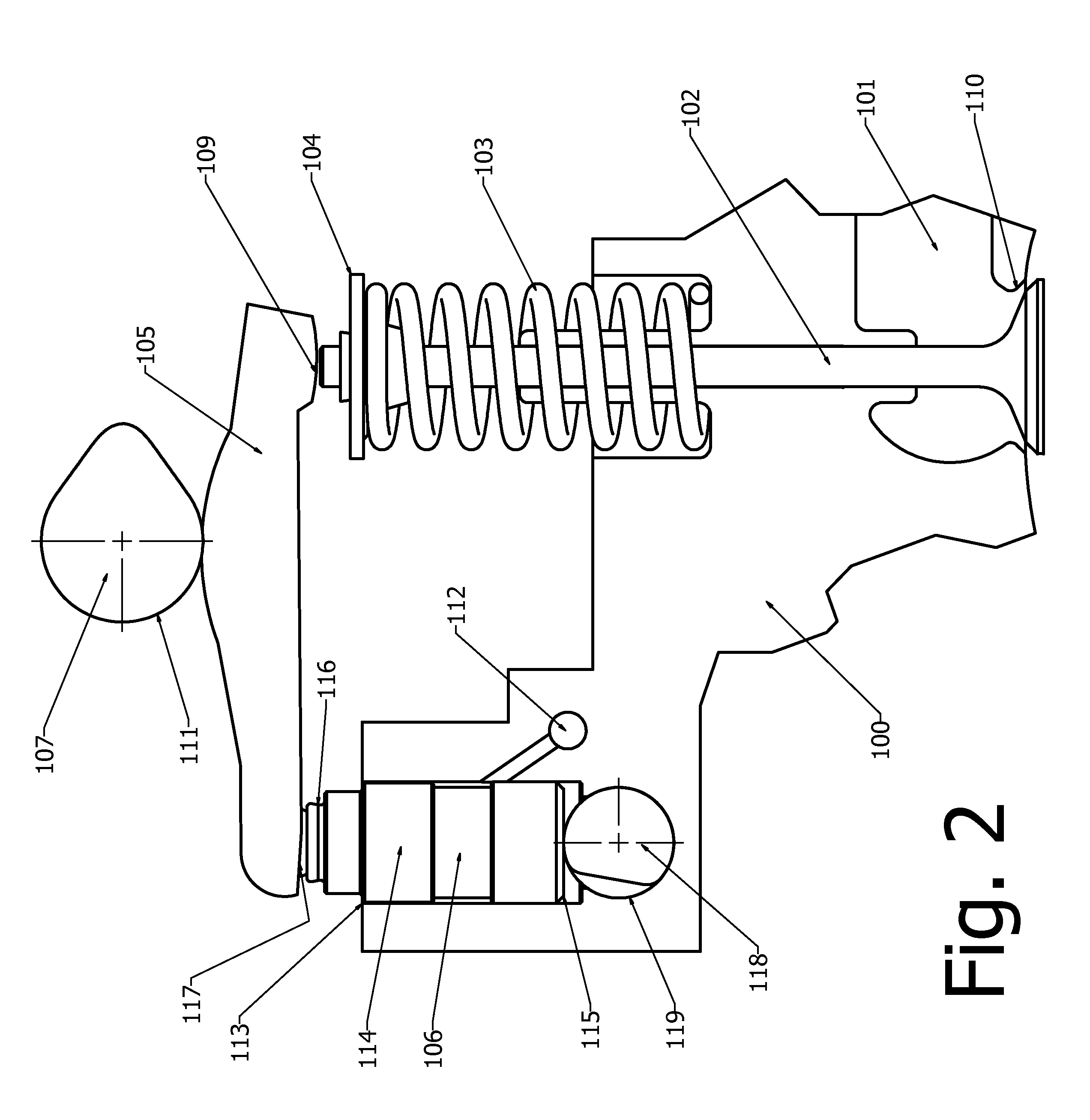
[0018]The cam operated compression release mechanism according to the present invention is illustrated in FIG. 1 and FIG. 2. The cylinder head 100 incorporates a gas flow port 101 with a poppet valve 102 that serves to open and allow gas flow in or out of the cylinder volume or close to confine the gas in the cylinder during the compression and expansion strokes. The poppet valve is biased in the closed position by a spring 103 acting through the spring retainer 104. A rocker arm 105 pivoted on a lash adjuster 106 engages a rotating cam 107 with a lobe 108 work together to periodically open the poppet valve by pressing on valve stem tip 109. The spring 103 is compressed as the valve opens, and then expands to close the valve. In the normal operating mode shown in FIG. 1 the valve closes fully and seals against the valve seat 110 when the cam base circle 111 is in contact with the rocker arm 105, thereby preventing gas flow in or out of the cylinder. The lash adjuster 106 is an oil-f...


PUM


Abstract

The present invention comprises apparatus and methods for releasing internal combustion engine compression during cranking to reduce cranking effort and the size and weight of the starter motor and battery. It is particularly suitable for fuel conservation systems that stop the engine when the vehicle is stopped in traffic, and restart the engine when the driver steps on the accelerator petal, since such systems place heavy demands on the starter motor and battery. The apparatus provides a means for automatically shifting the valve gear such that exhaust and/or inlet valves are held slightly open during the intake compression strokes to reduce compression torque during initial cranking, and restoring the valves to normal operation before the first firing event. The method provides a sequence of steps executed by the engine electronic control module to control the compression release apparatus to carry out the engine starting process safely and reliably.

Description

CROSS-REFERENCE TO RELATED APPLICATIONS[0001]This application claims the benefit of U.S. provisional application Ser. No. 61 / 687,835 filed May 2, 2012.FIELD OF THE INVENTION[0002]The present invention is related to methods and apparatus for temporarily reducing the compression pressure in reciprocating internal combustion engines during startup cranking, thereby reducing the cranking torque and energy required from the engine starting system. In particular, it is related to such methods and apparatus applicable to multi-cylinder vehicle engines that may be stopped and started frequently to reduce the fuel consumed while the vehicle is not moving.BACKGROUND OF THE INVENTION[0003]Significant fuel consumption savings may be gained in city driving by stopping the engine while the vehicle is stopped, and cranking and re-starting the engine automatically when the driver steps on the accelerator pedal. This repetitive cranking, however, places high torque and energy demands on the starting...

Claims


Application Information

Patent Timeline
IPC IPC(8): F01L1/24
CPCF01L1/2405F01L13/0031F01L13/06
Inventor MEACHAM, G. B. KIRBY
Owner MEACHAM G B KIRBY
Why Eureka
Try Eureka