

Fuel cell system and method for operating the same
a fuel cell and system technology, applied in the field of fuel cell systems, can solve the problems of fuel cell stack deterioration, fuel cell of this type can experience problems relating to the durability of solid-state polymer fuel cells, and the voltage of the fuel cell stack rises, so as to limit the deterioration caused by increased voltage and preserve fuel
- Summary
- Abstract
- Description
- Claims
- Application Information
AI Technical Summary
Benefits of technology
Problems solved by technology
Method used
Image

Examples
first embodiment
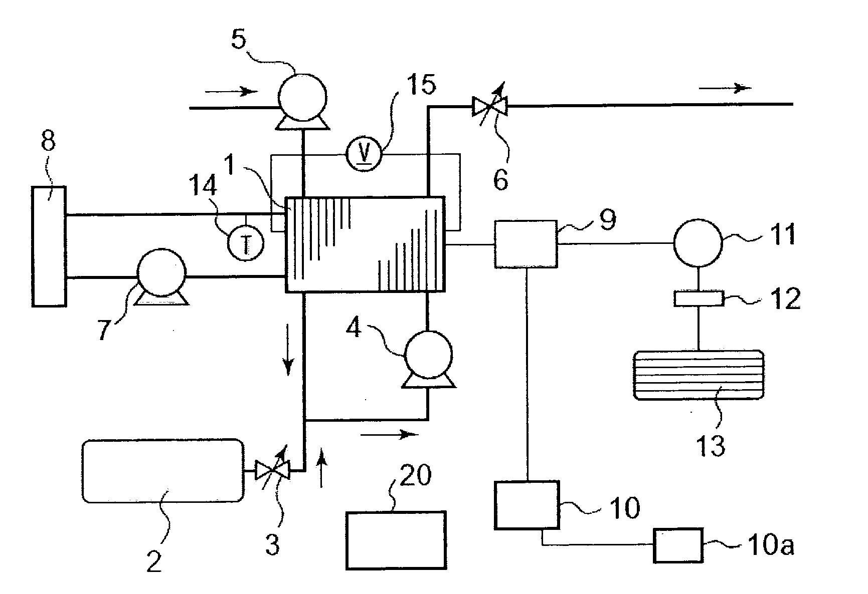
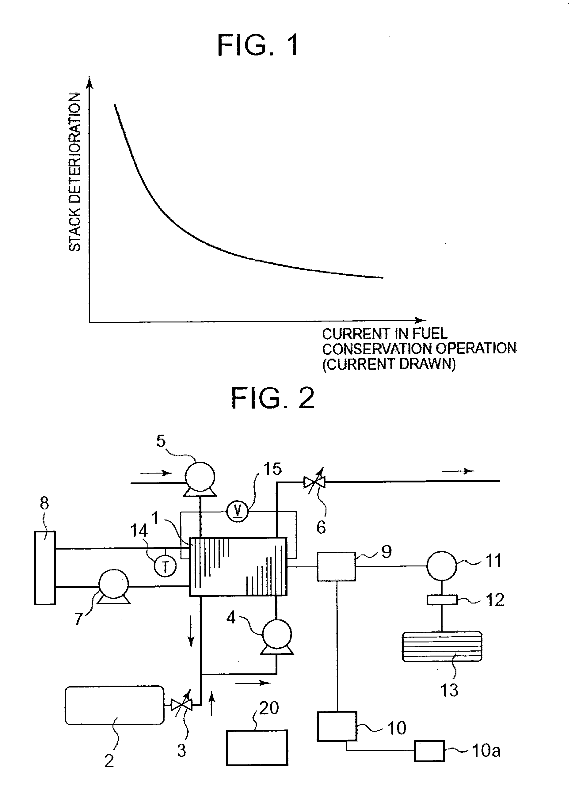
[0031]A first embodiment of the fuel cell system in accordance with the present invention will now be explained. FIG. 2 is a diagram illustrating an example of the main portion of the fuel cell vehicle carrying the fuel cell system according to this embodiment of the present invention. As shown in FIG. 2, fuel cell stack 1 is a laminate prepared by laminating plural solid-state polymer fuel cells. Fuel tank 2 stores hydrogen gas at high pressure as the fuel gas. Fuel pressure adjusting valve 3 reduces the high pressure of the hydrogen gas in fuel tank 2, whereupon the hydrogen gas is fed to fuel cell stack 1. Fuel gas circulating pump 4 mixes the fuel gas fed from fuel pressure adjusting valve 3 and the fuel gas exiting fuel cell stack 1, and feeds the mixture to fuel cell stack 1. Oxidant gas compressor 5 compresses air as the oxidant gas and feeds it to fuel cell stack 1. The air used in fuel cell stack 1 is released via oxidant gas pressure adjusting valve 6.
[0032]Cooling water c...
second embodiment
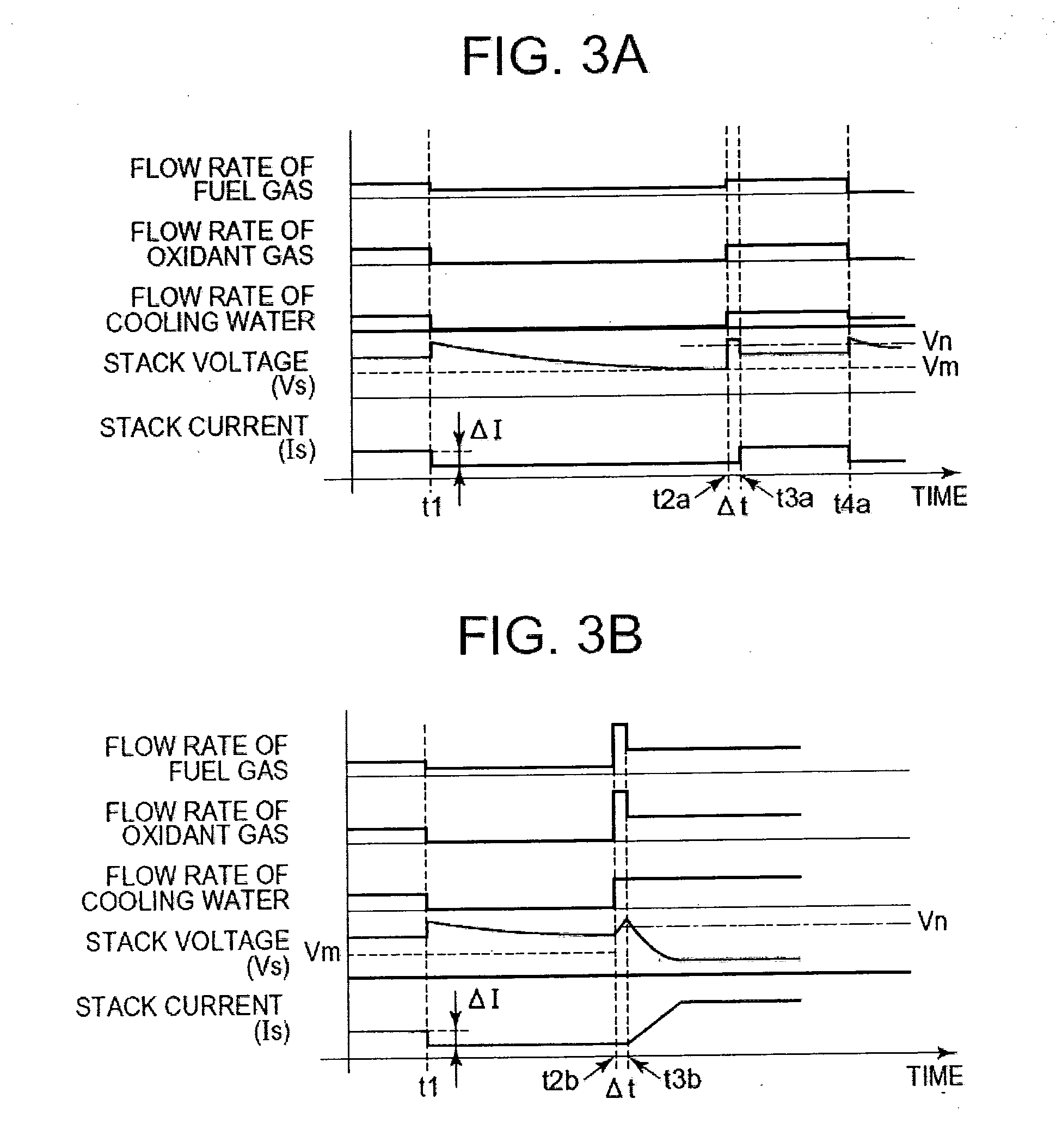
[0071]A second embodiment of the fuel cell system of the present invention will be explained. The constitution of the fuel cell system in this second embodiment is the same as that in the first embodiment as shown in FIG. 2. However, unlike the first embodiment in which stack current Is drawn from fuel cell stack 1 is reduced immediately after the start of the fuel conservation operation, in this second embodiment, a current equal to the stack current in idle operation is drawn during a certain period after shutdown of the auxiliary devices, and control is performed so that the stack voltage is quickly lowered. Another difference is that the current drawn curve has a sloping shape from the time of gas supply (when the voltage rises) in resetting to the idle operation. With the exception of what will be explained below, the second embodiment is essentially identical to the first embodiment.
[0072]FIG. 5 is a time chart illustrating an example of the various control values of the fuel ...
third embodiment
[0084]A third embodiment of the fuel cell system of the present invention will now be explained. The fuel cell system in this embodiment is similar to that of the first embodiment shown in FIG. 2, except that a discharge device (e.g., discharge means) is provided (not shown in FIG. 2) that can be connected in parallel with fuel cell stack 1. Unlike the first embodiment, in which the residual charge of rechargeable battery 10 is not considered in setting the current drawn from fuel cell stack 1 in fuel conservation operation, in this third embodiment the value of the current drawn from fuel cell stack 1 in fuel conservation operation is set at larger value when the residual charge of rechargeable battery 10 is smaller. With the exception of what is explained in the following, this embodiment is substantially identical to the first embodiment.
[0085]FIG. 7 is a time chart illustrating an example of the various control values of the fuel gas flow rate, oxidant gas flow rate, cooling wat...
PUM
| Property | Measurement | Unit |
|---|---|---|
| speed | aaaaa | aaaaa |
| voltage | aaaaa | aaaaa |
| voltage | aaaaa | aaaaa |
Abstract
Description
Claims
Application Information