Electronic accelerator pedal with high-linearity output signal

An electronic accelerator pedal and pedal technology, which is applied in engine control, machine/engine, mechanical equipment, etc., can solve the problem of low linearity of the output signal and achieve the effect of increasing comfort

Active Publication Date: 2011-07-13
WENZHOU RUILI KEMI AUTOMOTIVE ELECTRONICS CO LTD
View PDF7 Cites 5 Cited by
  • Summary
  • Abstract
  • Description
  • Claims
  • Application Information

AI Technical Summary

Problems solved by technology

However, the linearity of the accelerator pedal to the output signal of the electronic accelera...

Method used


Image

  • Electronic accelerator pedal with high-linearity output signal
  • Electronic accelerator pedal with high-linearity output signal
  • Electronic accelerator pedal with high-linearity output signal

Examples


Embodiment Construction

[0029] The present invention will be described in detail below in conjunction with the accompanying drawings.

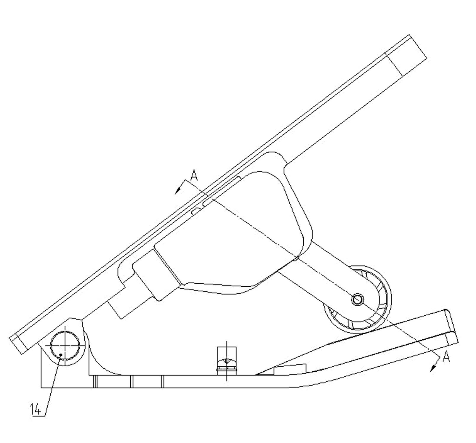
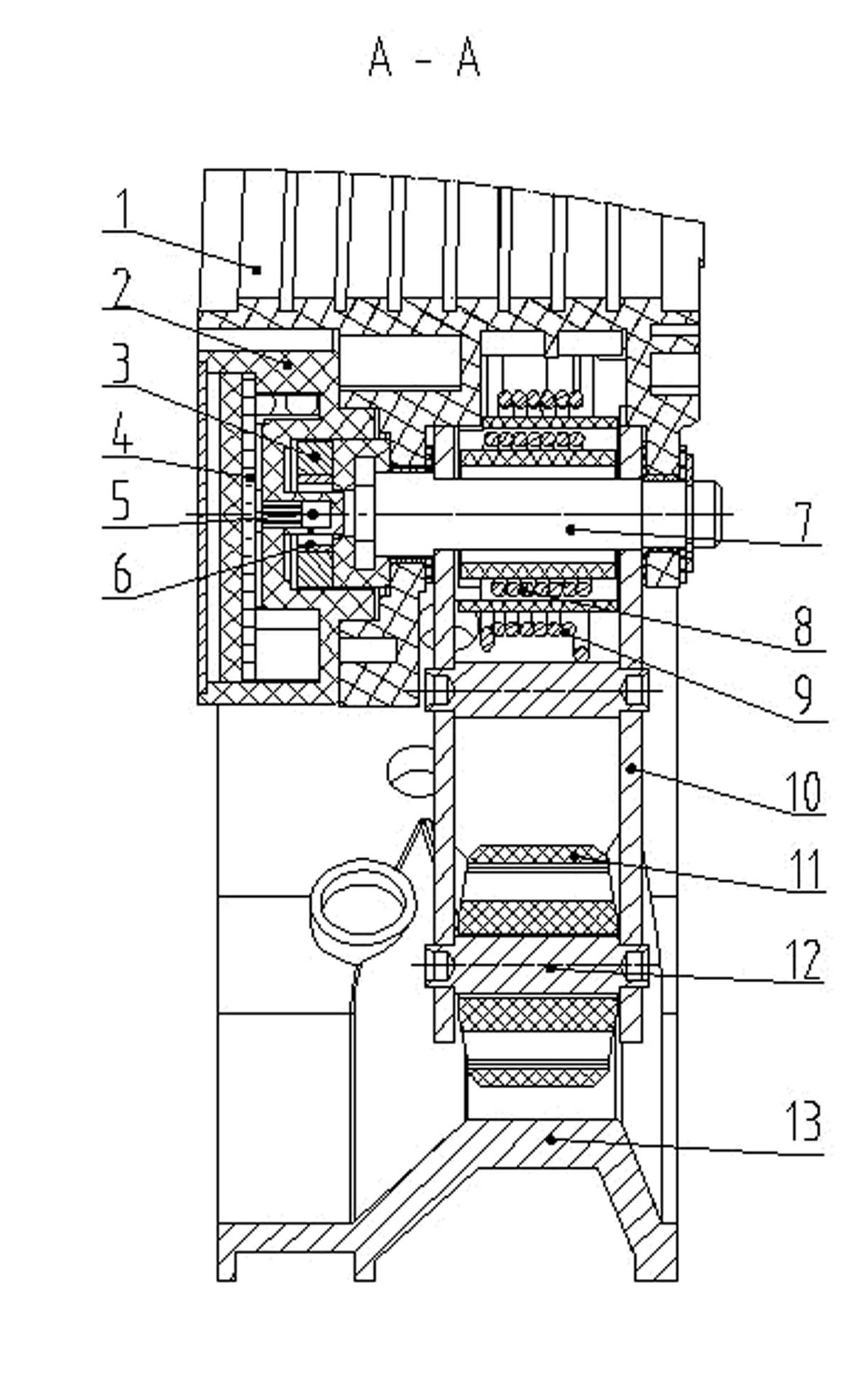
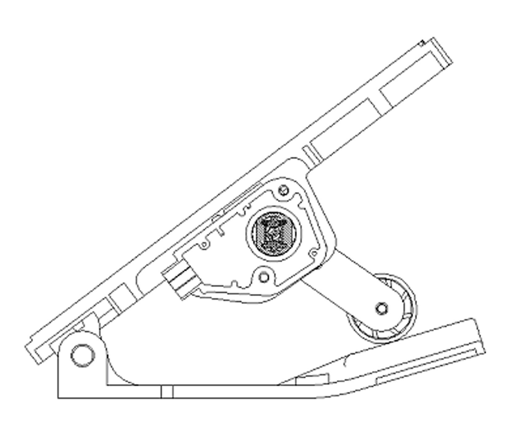
[0030] Such as figure 1 and figure 2 As shown, the electronic accelerator pedal assembly of the present invention has a base plate 13 and a pedal 1, the base plate and the pedal are both approximately rectangular, and pin seats are processed on the adjacent surfaces of one end of them, and horizontal pin holes are processed on the corresponding positions of the pin seats. , The two are movable and hinged together by pin shaft 14 and these pin holes. Bearing pin 14 wherein is covered with torsion spring, torsion spring two ends are respectively fixed on the pedal 1 and on the base plate 13. The bottom plate 13 here tilts up obliquely upwards from the far end of the pin shaft 14, and a boss on which the roller 11 rolls is set on the tilted surface. Base plate 13 adopts multi-shaped surface structure and surface spraying. The design of the pedal 1 here includes the...


PUM


Abstract

The invention relates to an electronic accelerator pedal with a high-linearity output signal, which belongs to an accelerator control device of a motor vehicle and relates to a non-contact electronic accelerator pedal for oil inlet amount of an engine cylinder of the motor vehicle. The conventional non-contact electronic accelerator pedal is improved by setting the direction of magnetic steel in a Hall sensor when the engine is in different states and setting the angle of the Hall sensor between 26 degrees and 40 degrees at an idle speed position. Based on the improvement, the electronic accelerator pedal assembly in the invention solves the problems of difficulty in accurate control over the initial position of the conventional electronic accelerator pedal sensor, poorer linearity of a voltage output signal responding to the electronic accelerator pedal and poor operational reliability of an electronic accelerator so that the accelerator control accuracy of the engine is improved, fuel oil is saved and the environment is protected.

Description

technical field [0001] The invention relates to an electronic accelerator pedal assembly, which belongs to an accelerator control device of a motor vehicle, and relates to a non-contact electronic accelerator pedal assembly of the fuel intake amount of a motor vehicle engine cylinder. Background technique [0002] As we all know, in order to control the oil intake of the cylinder of the motor vehicle, and then control the rotational speed and power of the engine, to finally realize the control of the speed of the motor vehicle. Therefore all be provided with accelerator pedal in the cab of motor vehicle. Most of the traditional accelerator pedals realize the control of the opening of the accelerator through connecting rods or cables, and a series of actions are mechanical movements. Because a series of actions of this accelerator pedal are all mechanical movements, its transmission precision and sensitivity are not high. However, the ordinary contact-type electronically co...

Claims


Application Information

Patent Timeline
IPC IPC(8): F02D11/10
Inventor 黄权何念权陈亮
Owner WENZHOU RUILI KEMI AUTOMOTIVE ELECTRONICS CO LTD
Why Eureka
Try Eureka