
Airway device

Inactive Publication Date: 2010-11-18
NASIR MUHAMMED ASLAM
View PDF69 Cites 50 Cited by
  • Summary
  • Abstract
  • Description
  • Claims
  • Application Information

AI Technical Summary

Benefits of technology

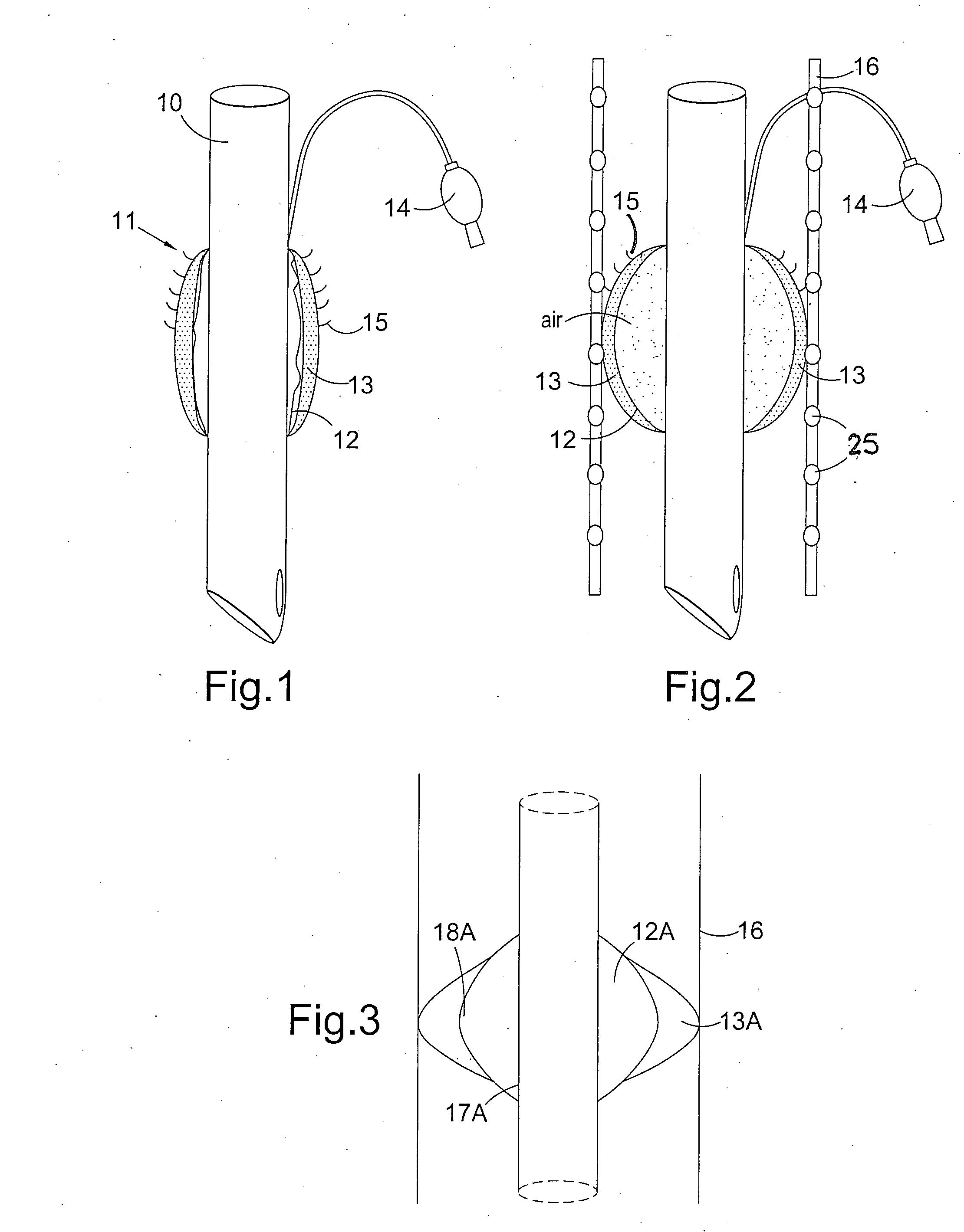
[0014]Accordingly, according to a first embodiment, there is provided an airway device for insertion into the trachea or bronchi of a human or animal comprising an elongate flexible tube having a distal end, a proximal end and a lumen therethrough, the device further comprising a cuff located at or near the distal end of the flexible tube, wherein the cuff comprises an inner inflatable region and an outer soft barrier region adapted to prevent the walls of the airway coming into direct contact with the inner inflatable region when the cuff is in position and inflated.
[0015]The airway device according to the present invention provides major advantages over prior designs. The design is suitable for, among other things, use as or along with an endotracheal or an endobronchial tube. The outer soft barrier region can serve a dual purpose. Because of its softness, it does not damage the tissues surrounding the cuff when it is inflated. Therefore, the cuff provides a sufficient seal without damaging the soft delicate tissue around the device.
[0016]Furthermore, the outer barrier layer reduces the chance of leakage of fluid around the cuff because the barrier layer does not form the longitudinal folds that allow aspiration around the cuff.

Problems solved by technology

Furthermore, the outer barrier layer reduces the chance of leakage of fluid around the cuff because the barrier layer does not form the longitudinal folds that allow aspiration around the cuff.

Method used


Image

  • Airway device
  • Airway device
  • Airway device

Examples


first embodiment

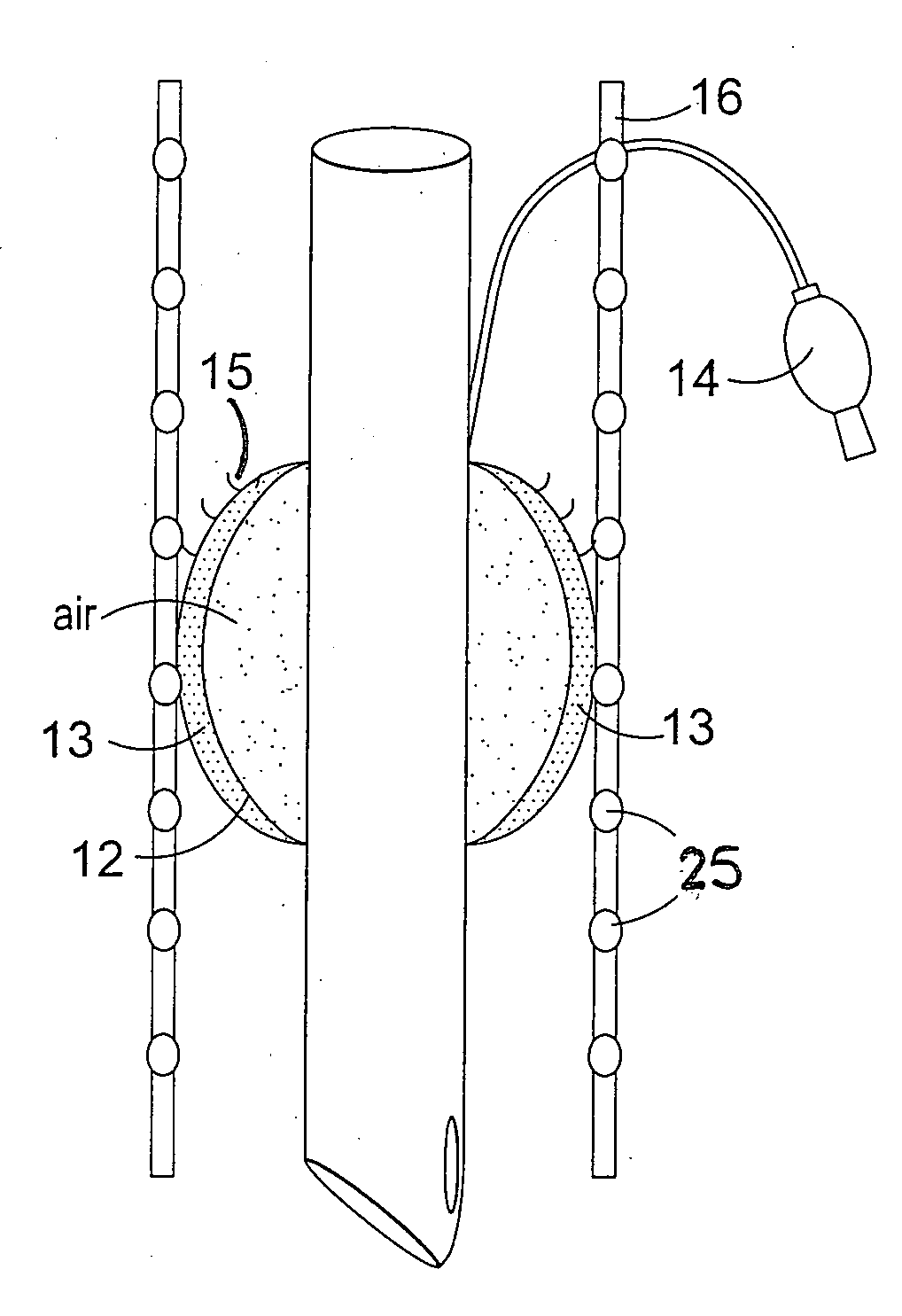
[0092]FIG. 1 shows an endotracheal device according to the present invention. The device is shown in an un-inflated or deflated position. The device comprises an airway tube 10 and a cuff 11. The cuff, or in this case cuff assembly, is made up of an inner inflatable region 12 and a soft outer barrier region 13 together with means to inflate the inner inflatable region 14. The inner region 12 is similar to the inflatable cuffs known in the prior art although it has a smaller profile to accommodate the presence of the outer barrier region. Typically, the inner barrier region will expand enough to allow a good seal to form between the outer barrier region and the walls of the trachea. The inner inflatable region can be of a lower compliance than would otherwise be desirable as it does not come into contact with the trachea, in use, and therefore it will not damage the soft tissue. In addition, a higher cuff pressure can be applied because, again, it does not come into contact with the ...

third embodiment

[0124]FIG. 6 shows the present invention. It shows an airway tube 30 which has a first substantially straight tubular region 31 and a second tubular region 32 that extends at an angle from the longitudinal axis of the first tubular region, the second tubular region further comprising a cuff assembly 33 and incorporating the distal end of the tube 34. An inflation means 35 for the cuff assembly is also shown. An angled airway tube can be incorporated into any of the embodiments described herein.

[0125]The second tubular region 32 can be separated from the first tubular region 31 by a section 36 that enables the offset angle of region 32 to be adjusted. This can take the form of a concertina arrangement or a material that can be adjusted into a particular conformation and remain in that conformation during the process of intubation. As soon as the intubation is accomplished the lower tubular part adjusts its shape to the longitudinal axis of the trachea. This arrangement not only helps...


PUM


Abstract

An airway device for insertion into the trachea or bronchi of a human or animal, comprising an elongate flexible tube (10) having a distal end, a proximal end and a lumen therethrough, the device further comprising a cuff (11) located at or near the distal end of the flexible tube, wherein the cuff comprises an inner inflatable region (12) and an outer soft barrier region (13) adapted to prevent the walls of the airway coming into direct contact with the inner inflatable region when the cuff is in position and inflated.

Description

FIELD OF THE INVENTION[0001]This invention relates to an airway device. It is particularly applicable, but in no way limited, to devices used in the administration of anaesthetic gases and oxygen to a patient breathing spontaneously, during intermittent positive pressure ventilation for a surgical procedure, during cardiopulmonary resuscitation or for ventilatory support in intensive care. The present invention also relates in particular to an endotracheal, endobronchial or a combined endotracheal / endobronchial airway device. More specifically, the present invention relates to an endotracheal airway device that is safer and easier to use than known endotracheal airway devices, that provides a greater degree of protection to the patient against aspiration, and to methods of fabricating such an airway device.BACKGROUND TO THE INVENTION[0002]Endotracheal intubation is a common medical procedure and endotracheal tubes are used in many situations for ventilatory purposes. They are used i...

Claims


Application Information

Patent Timeline
IPC IPC(8): A61M16/04A61M5/00A61C5/14
CPCA61M16/04A61M16/0434A61M25/04A61M2205/583A61M16/0415A61M16/0418A61M16/0436A61M16/0443A61M16/0445A61M16/0447A61M16/0456A61M16/0479A61M16/0493
Inventor NASIR, MUHAMMED ASLAM
Owner NASIR MUHAMMED ASLAM
Learn More