[0010]A draft protection device of the present invention protects the weighing compartment of an associated laboratory instrument from the effects of air movements while also overcoming the problems associated with known devices. As the horizontally slidable sidewall is subjected to a biasing torque that is directed against the floor, the side wall is pushed against the border edge of the floor. The
contact pressure of the sidewall against the adjacent border edge provides an adequate seal between the sidewall and the adjacent border edge. Neither production tolerances of the parts of the draft protection device nor the property of the top cover to be vertically movable together with at least one wall as described hereinafter can lead to gaping crevices and, thus, to leaks in the draft protection device. Furthermore, with the design according to the present invention for the guiding constraint of the sidewall, the latter is supported in a statically determinate way. Particularly, the fact that the sidewall cannot swing in and out like a
pendulum leads to stability of the entire draft protection device. Of course, the same applies analogously to the front wall and its holder means.
[0012]As a result of its own weight, the sidewall is kept in stable engagement with the guide rails by the guiding flank, the border edge, and the loose swivel fulcrum. Consequently, the larger the downward pull of its own weight, the more resistant the horizontally slidable sidewall will be against being swayed by air movements of the ambient
atmosphere.
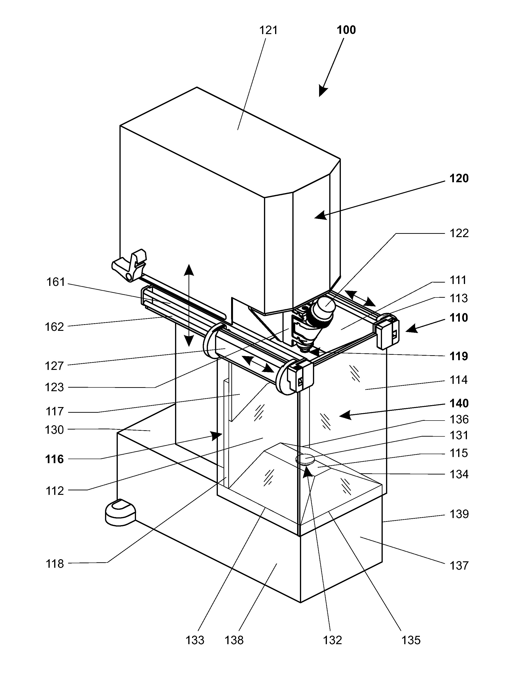
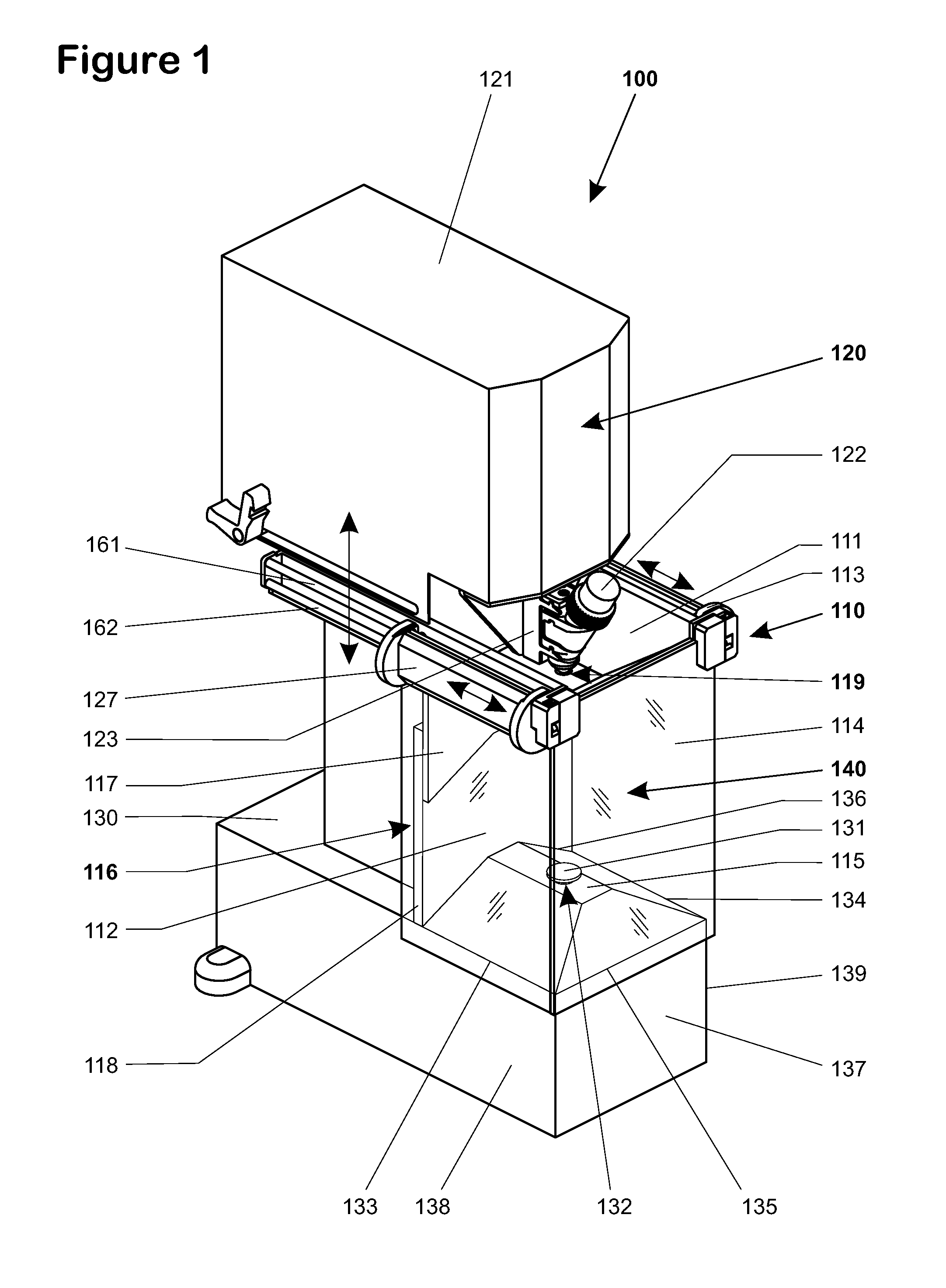
[0015]In an alternative embodiment, a first guide rail and, extending parallel thereto, a second guide rail, are arranged on the side of the top cover that faces towards the sidewall. The slidable sidewall has at least one guide element that contains at least one rigidly held first guide roller and a second guide roller that is held by a tiltable pivot and biased by an elastic element. The first guide roller on the first guide rail serves to support the weight of the slidable sidewall and to constrain the sidewall against
lateral movement, i.e., movement orthogonal to the sliding direction. The slidable sidewall is further elastically biased towards the second guide rail by the tiltable second guide roller and is therefore subjected to a torque which urges the sidewall towards the floor, where the torque is supported by the border edge against the sidewall.
[0019]Given that a draft protection device should as much as possible keep out all air movements that are present in the environment of the laboratory instrument, it is beneficial if a sealing glide strip, sealing
brush or sealing roller, is arranged along at least one border edge of the floor to extend at least over the length of the border edge. This serves to seal a possibly existing gap between the border edge of the floor and the sidewall while simultaneously allowing the sidewall to glide smoothly over the border edge. For sidewalls with a particularly damage-prone surface, for example coated glass panels, one could also use a sealing roller which rolls on the sidewall when the latter is moved vertically and which has sufficiently smooth-gliding surface properties for a horizontal movement of the sidewall. Should these measures still be inadequate, one could of course also arrange a supporting roller ball or a row of roller balls along the border edge of the floor, so that independently of the direction of movement there is never a
sliding contact movement taking place between the roller balls and the sidewall because the direction of the rotary movement of the roller balls adapts itself to the movement of the sidewall. The gaps between the individual roller balls or the recesses between their contact points with the sidewalls may be sufficiently filled out, for example, with
brush segments or sealing strip segments, so that no gap or only an extremely small gap remains between two neighboring roller balls and the sidewall that lies against the roller balls. Leaks in the areas of the vertical edges of the draft protection device, which may occur as a result of angular misalignments of the front wall, the rear wall and the sidewalls in relation to each other, can be closed by arranging soft-elastic sealing lips or brushes in the vertical border areas of these walls.
[0020]It is further known in practice that the volume of the weighing compartment can limit the precision of a balance. The reason for this is that the enclosed air in a large weighing compartment is influenced much more strongly by the environment outside of the draft shield, for example by the incoming heat and light
radiation. Further, in a large weighing compartment there are, in proportion to the enclosed volume, fewer surfaces slowing the
air movement, for example after the sidewall has been closed. It therefore helps if the weighing compartment has a small volume in order for the air inside the weighing compartment to come to rest very quickly. Furthermore, the air in a weighing compartment of limited height is shifted about only to a
minimal extent and it takes only a relatively short time for the air inside the weighing compartment to settle into a stable temperature profile over the height of the weighing compartment.
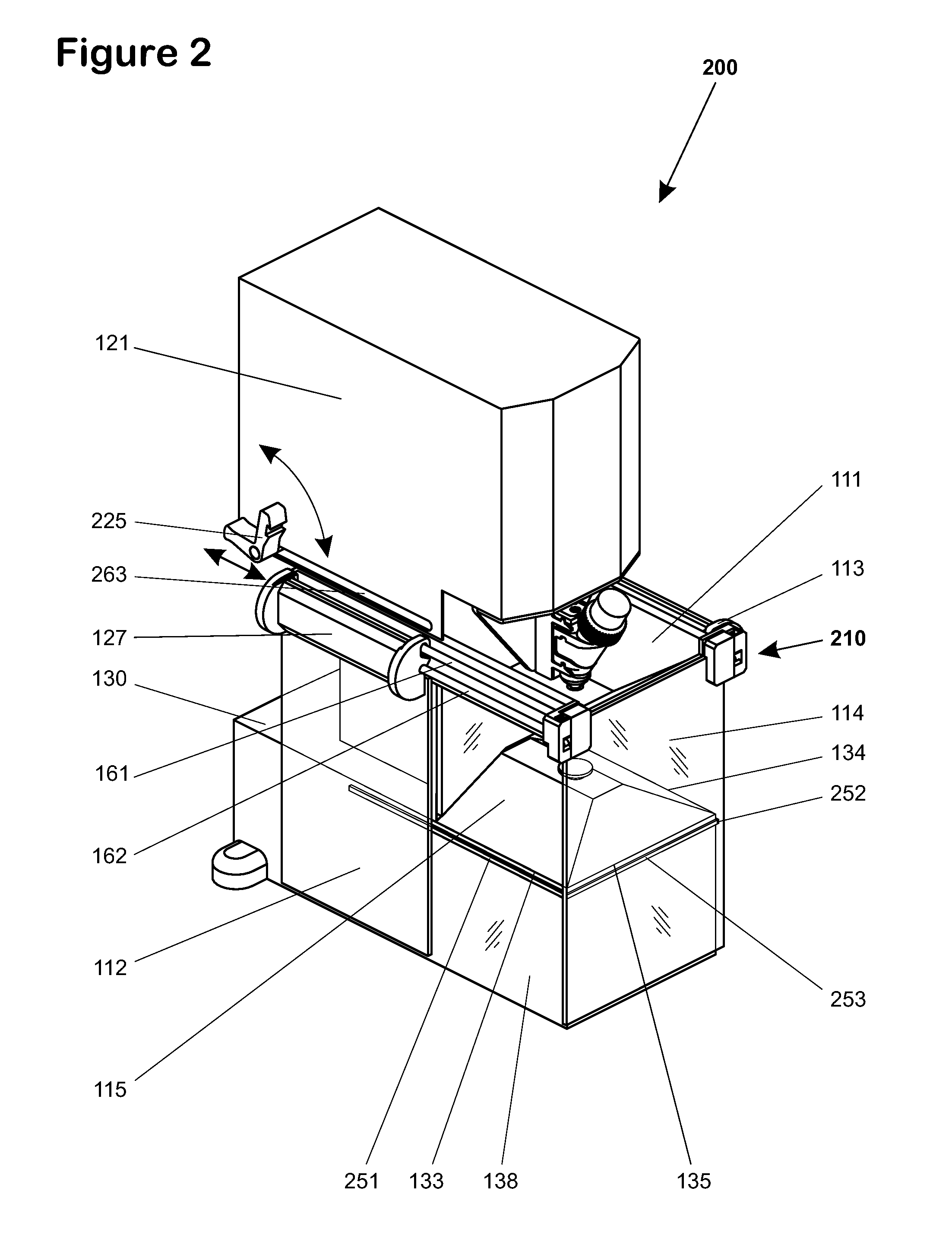
[0021]It is therefore advantageous if the top cover and at least one of the two sidewalls and / or the front wall and / or the rear wall are vertically slidable relative to the floor. This is facilitated by the inventive guiding arrangement of the sidewalls, as there are no guiding devices whatsoever in the area of the floor standing in the way of a vertical movement of this kind. It is only necessary that the housing walls of the laboratory instrument which adjoin the border edges of the floor be configured in such a way that the vertically movable walls can slide vertically past those border edges.

