Spooling arrangement for continuous composite sucker rod

a composite sucker rod and spooling technology, which is applied in the direction of web handling, drilling pipes, transportation and packaging, etc., can solve the problems of limiting the length of the rod that can be stored on the reel, presenting a time-consuming and labor-intensive process, and about 300 feet of rod length

Inactive Publication Date: 2010-11-18
JOHN CRANE PRODION SOLUTIONS
View PDF18 Cites 18 Cited by
  • Summary
  • Abstract
  • Description
  • Claims
  • Application Information

AI Technical Summary

Problems solved by technology

Such rod sections are typically threaded end to end and present a time consuming and labor intensive process for installing, uninstalling, or repairing sucker rods.
Although the use or ribbon rods in general is an improvement over the steel tubing sections used in the past, the finite length of rod that can be stored on a reel is limited, for example, to about 300 feet.
Even though reels can be made larger to accommodate longer rod lengths, the requirement of having reels that are of a manageable size for mounting onto a truck bed and for transporting to well locations lim

Method used


Image

  • Spooling arrangement for continuous composite sucker rod
  • Spooling arrangement for continuous composite sucker rod
  • Spooling arrangement for continuous composite sucker rod

Examples


Embodiment Construction

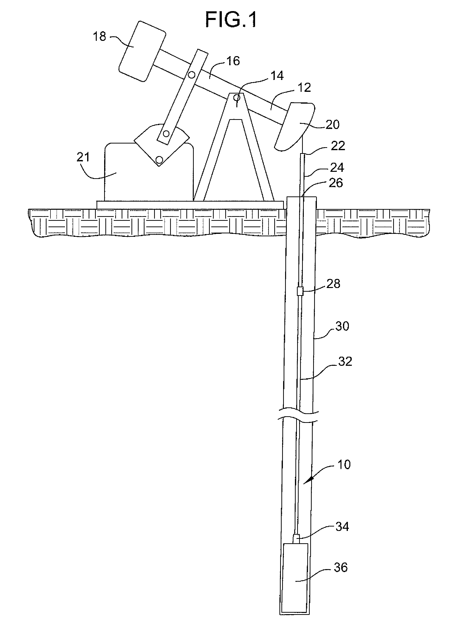
[0019]A continuous fiberglass rod 10 for use in a wellbore 30 is shown in FIG. 1. As used herein, “continuous” fiberglass rod means fiberglass rods that are continuous, i.e. either without interconnections or with very few interconnections, from near the surface to near the bottom of the well 30. The continuous fiberglass rod 10 connects between a pump jack 12 and a down-hole pump 36. In the illustrated embodiment, a coupling 28 is shown connected along the length of the rod 10.

[0020]Continuous composite fiberglass rod 10 may be reciprocated utilizing the pump jack 12. A typical pump jack may comprise a head 20, a beam 16, and a counterweight 18 pivotally mounted to support a frame 14. A pump jack motor 21 may be utilized to pivotally move a beam 16, and a connector 22 may be utilized to connect the head 20 to a fiberglass polished rod 24. The polished rod 24 can extend through a seal 26, which may comprise a pack-off or other sealing mechanism. The connector 28 may be utilized to c...


PUM


Abstract

A coiling arrangement for a continuous composite sucker rod for a well sump includes a spool having a substantially cylindrical shape. A support structure rotatably supporting the spool about a rotation shaft, and for translatory movement. A guide arrangement moves the spool reciprocally such that the reciprocal motion of the support structure is along a direction that is parallel to the axis of rotation of the shaft. The rod is thereby accumulated on the spool in a spiral manner with minimal lateral deflection. In one form the spool is reciprocal relative to its support shaft. In another a support structure is reciprocal with the spool.

Description

CROSS-REFERENCE TO RELATED APPLICATIONS[0001]This patent application claims priority pursuant to Title 35 USC §119 to U.S. Provisional Patent Application No. 61 / 178,313, which was filed on May 14, 2009, and which is incorporated herein in its entirety by reference.BACKGROUND OF THE INVENTION[0002]Oil well pumping systems typically use a rod that interconnects a reciprocal pump that is located at the bottom of a well to a reciprocating actuator on the surface. The rod, which is commonly referred to as a sucker rod, transfers the reciprocal motion of the actuator to the pump. A typical well may have a depth of 5,000 feet or more (about 1,500 meters or more).[0003]Conventional sucker rods are made of steel tubing that is assembled in sections, for example, 32-foot sections, while being inserted or removed from a well. Such rod sections are typically threaded end to end and present a time consuming and labor intensive process for installing, uninstalling, or repairing sucker rods.[0004]...

Claims


Application Information

Patent Timeline
IPC IPC(8): B65H16/02
CPCB65H54/2803B65H75/285E21B19/22B65H2701/3914B65H75/425
Inventor RUTLEDGE, SR., RUSSELL P.
Owner JOHN CRANE PRODION SOLUTIONS
Why Eureka
Try Eureka