Fluorescence-based pipette instrument

a fluorescence-based pipette and instrument technology, applied in instruments, material analysis using wave/particle radiation, laboratory glassware, etc., can solve the problem of time and resource consumption of cell counting under microscope using this approach

Inactive Publication Date: 2010-11-18
ORFLO TECH LLC
View PDF45 Cites 19 Cited by
  • Summary
  • Abstract
  • Description
  • Claims
  • Application Information

AI Technical Summary

Problems solved by technology

Unfortunately, counting cells under a microscope using this approach is very time and resource intensive, and count accuracy depends wholly on the number of cells a user is willing to actually count in the given volume.

Method used


Image

  • Fluorescence-based pipette instrument
  • Fluorescence-based pipette instrument
  • Fluorescence-based pipette instrument

Examples


embodiment 100

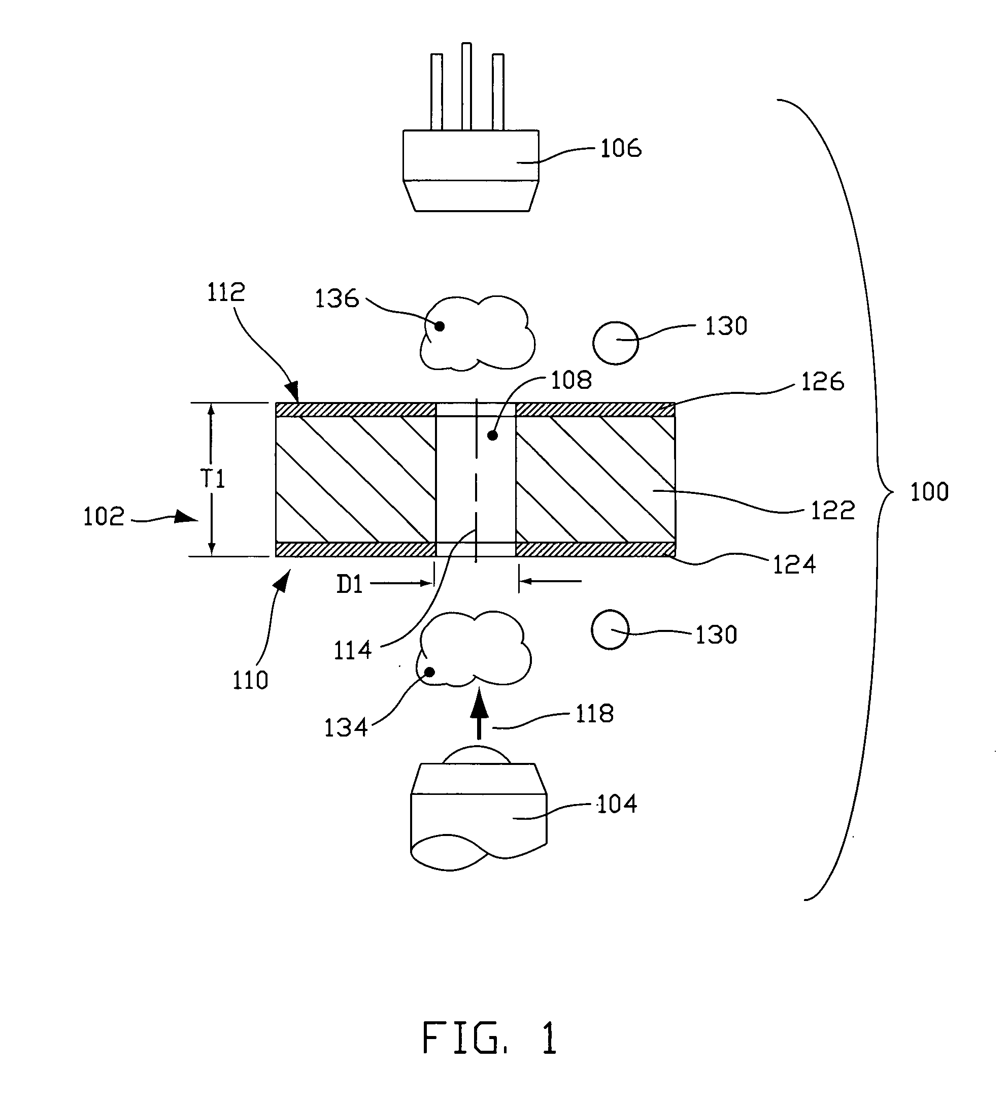
[0037]A schematic illustrating a generalized operable arrangement of structure employed in certain embodiments of the invention is indicated generally at 100 in FIG. 1. As illustrated, embodiment 100 includes an opaque member, generally indicated at 102, disposed between a radiation source 104 and a radiation detector 106. Sometimes, opaque member 102 may be made reference to as an interrogation layer, because layer 102 is associated with an interrogation zone. At least one orifice 108 is disposed in opaque member 102 to provide a flow path between a first side, generally indicated at 110, and a second side, generally indicated at 112. Orifice 108 may be characterized as having a through-axis 114 along which fluid may flow between the first and second sides 110 and 112 of opaque member 102, respectively.

[0038]The thickness, T1, of an opaque member and characteristic size, D1, of an orifice are typically sized in agreement with a size of a particle of interest to promote single-file ...

embodiment 140

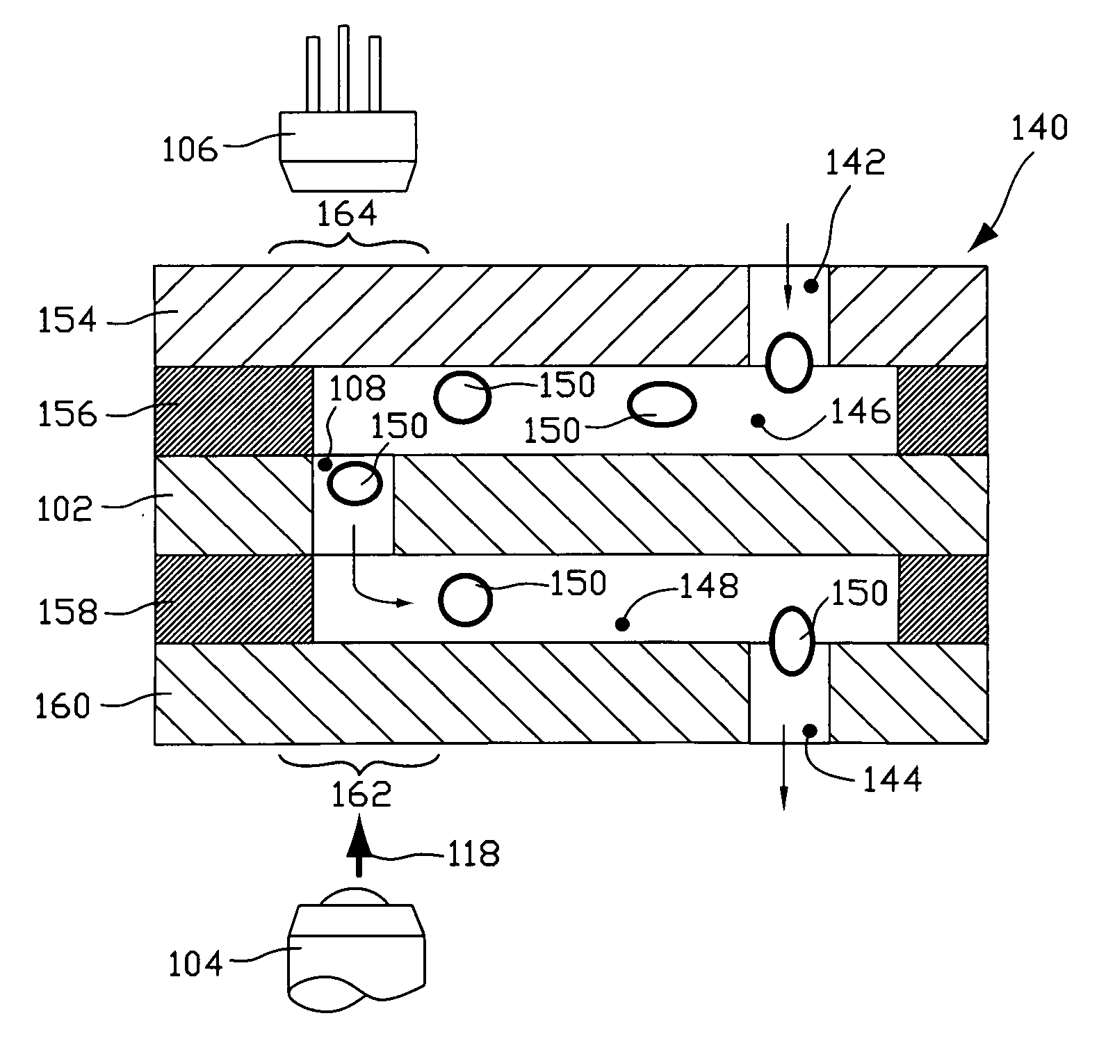
[0049]The multilayer plumbing arrangement 140 illustrated in FIGS. 2 and 3 includes a top cap layer 154, a top channel layer 156, an opaque member 102, a bottom channel layer 158, and a bottom cap layer 160. Such layers can be stamped, e.g. die cut, or manufactured by using a laser or water jet, or other machining technique, such as micro machining, etching, and the like. In a currently preferred embodiment 140 that is used to interrogate blood cells, certain of the various layers are typically made from thin polymer films, which are then bonded together to form the multilayer assembly. Desirably, the thickness of at least the channel layers 156, 158 are on the order of the characteristic size of particles of interest to promote single-file travel of particles through an interrogation zone. A workable thickness of such layers in currently preferred devices used to interrogate blood cells typically ranges between about 10 microns and about 300 microns.

[0050]In any case, at least a po...


PUM

PropertyMeasurementUnit
volumesaaaaaaaaaa
thicknessaaaaaaaaaa
thicknessaaaaaaaaaa

Abstract

An improved pipette tip (276) including an elongate body stretching between a proximal end (277) and a distal end. The body typically includes a plurality of thin film layers (e.g. 154, 156, 102, 158, 202) configured and arranged to provide a fluid path extending from the distal end toward the proximal end (277). The improved pipette tip (276) includes an interrogation zone in which to interrogate fluid flowing along the fluid path. One operable interrogation arrangement, generally (100), includes structure configured to permit detection of radiation resulting from a Stokes-shift. Optionally, a sensor component may include one or more electrode (e.g. 248, 250) that is disposed in the fluid path to contact fluid therein for electrically-based interrogation. A pipette tip (276) may be embodied to: count particles, verify sample integrity (e.g. freedom from bubbles), monitor sample flow rate, and confirm an inspired volume, among other uses.

Description

PRIORITY CLAIM[0001]This application claims the benefit of the filing date of U.S. Provisional Patent Application Ser. No. 61 / 004,630, filed Nov. 27, 2007, for “Fluorescence-based pipette instrument”, the entire contents of which are incorporated herein by this reference.TECHNICAL FIELD[0002]This invention relates to devices for extracting a fluid sample from a bulk fluid container for subsequent or simultaneous optical and / or electrical interrogation of the sample.BACKGROUND[0003]Handheld pipettes, which are used for precision fluid volume measurement and delivery, are some of the most common and widely-used laboratory tools available to scientists today. Many procedures requiring low-volume fluid handling of biological and chemical liquid samples rely on their ease of use, precision and repeatability to ensure proper, consistent experimental processing. Commercial pipettes are available in a wide variety of fixed and adjustable volumes. When used in large-scale, high-throughput te...

Claims


Application Information

Patent Timeline
Patent Type & Authority Applications(United States)
IPC IPC(8): G01N23/00
CPCB01L3/0217G01N2035/1062B01L3/50273B01L2200/0647B01L2200/0689B01L2300/025B01L2300/0645B01L2300/0654B01L2300/0874B01L2300/0887G01N15/10G01N21/05G01N21/645G01N21/65G01N35/10G01N2015/1062G01N2015/1486G01N2021/0346G01N2021/6482G01N2035/103G01N2035/1039B01L3/0275
Inventor AYLIFFE, HAROLD E.KING, CURTIS S.
Owner ORFLO TECH LLC
Why Eureka
Try Eureka