Electric rotating machine having improved stator coil arrangement for reducing magnetic noise and torque ripple

a stator coil and electric rotating machine technology, which is applied in the direction of synchronous machines, windings, dynamo-electric components, etc., can solve the problems of difficult to suitably arrange the coil ends of the first and second three-phase stator coils, and difficult to minimize the size of the electric rotating machine. , the effect of reducing the total magnetic noise and torque ripple generated in the rotating electric machin

Active Publication Date: 2010-11-18
DENSO CORP
View PDF9 Cites 36 Cited by
  • Summary
  • Abstract
  • Description
  • Claims
  • Application Information

AI Technical Summary

Benefits of technology

[0010]With the above configuration, since the first and second three-phase stator coils are wound in the concentrated winding manner, it is possible to suitably arrange the coil ends of the first and second three-phase stator coils and thereby minimize the size of the electric rotating machine. Moreover, with the phase difference of π/6 provided between the first and second three-phase stator

Problems solved by technology

In such an electric rotating machine, magnetic noise and torque ripple are generally caused by the overlapping of harmonic components with sine-wave drive currents supplied to the phase windings of the three-phase stator coil.
Consequently, it is difficult to suita

Method used


Image

  • Electric rotating machine having improved stator coil arrangement for reducing magnetic noise and torque ripple
  • Electric rotating machine having improved stator coil arrangement for reducing magnetic noise and torque ripple
  • Electric rotating machine having improved stator coil arrangement for reducing magnetic noise and torque ripple

Examples


first embodiment

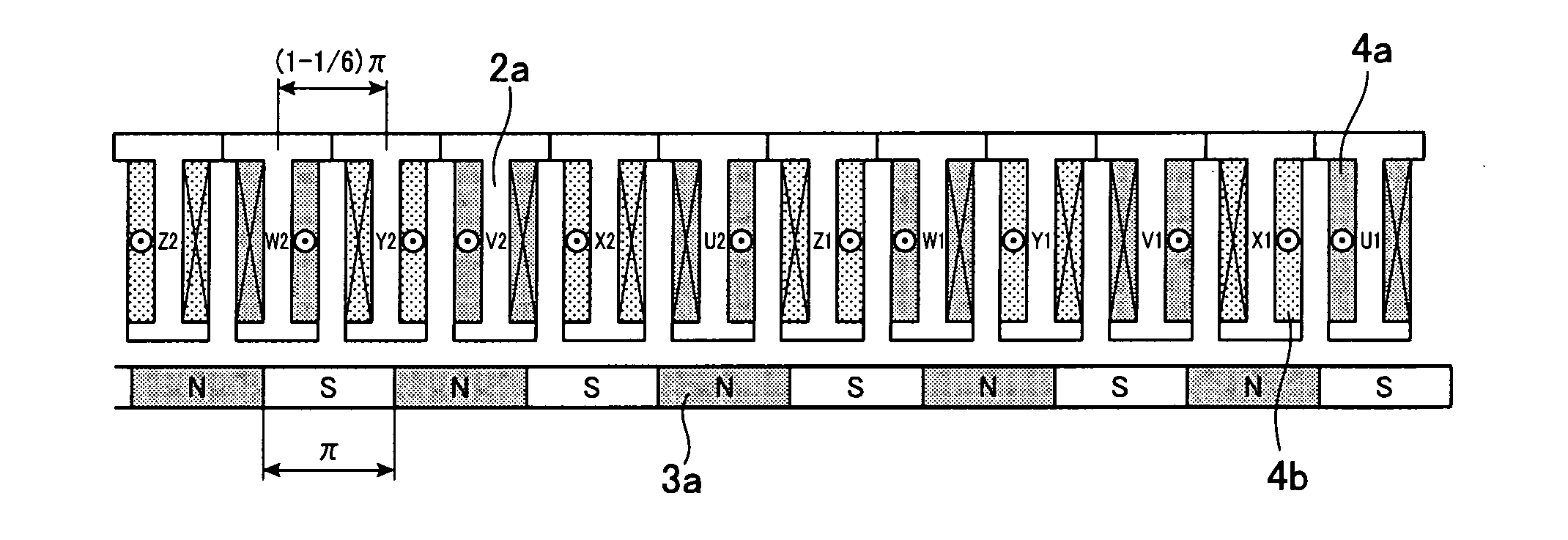
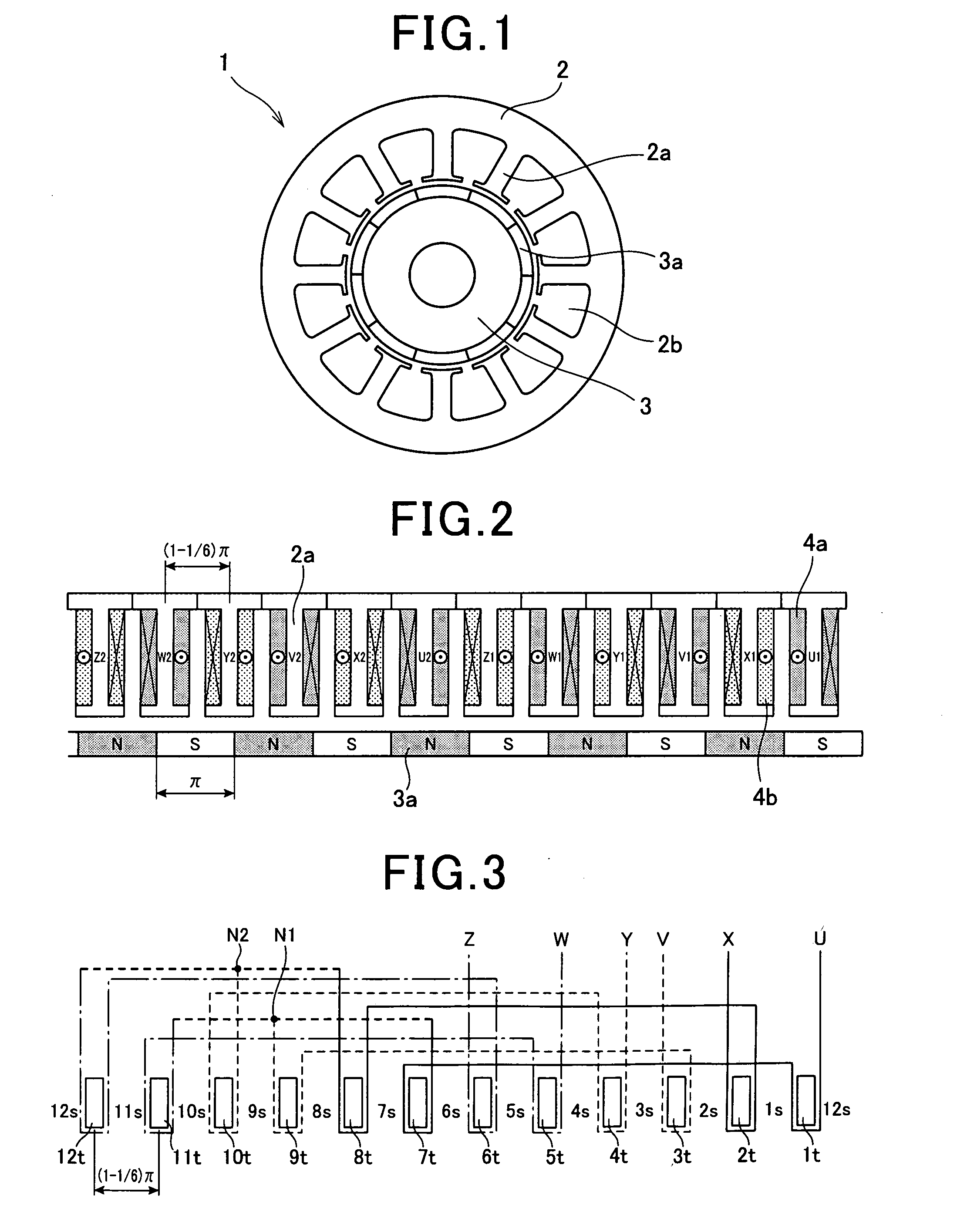
[0031]FIG. 1 shows the overall configuration of an electric rotating machine 1 according to the first embodiment of the invention. In the present embodiment, the electric rotating machine 1 is designed to function as an electric motor in a motor vehicle. As shown in FIG. 1, the electric rotating machine 1 includes a stator 2 and a rotor 3.

[0032]Referring further to FIG. 2 together with FIG. 1, the stator 2 includes a hollow cylindrical stator core and first and second three-phase stator coils 4a and 4b. The stator core has formed therein twelve stator core teeth 2a that protrude radially inward and are arranged in the circumferential direction of the stator core at a predetermined pitch. Between each circumferentially-adjacent pair of the stator core teeth 2a, there is formed a slot 2b. In other words, the stator core includes twelve slots 2b formed between the stator core teeth 2a.

[0033]The rotor 3 is rotatably disposed radially inside of the stator core 2. The rotor 3 has ten mag...

second embodiment

[0065]FIGS. 7 and 8 illustrate the configuration of an electric rotating machine 1 according to the second embodiment of the invention. It should be noted that for the sake of facilitating understanding, first and second three-phase stator coils 4a and 4b of the electric rotating machine 1, which are actually mounted on the same stator core, are separately shown in FIG. 8.

[0066]As shown in FIGS. 7 and 8, the stator core of the stator 2 and the rotor 3 in this embodiment are identical to those in the first embodiment. Accordingly, in this embodiment, the number of the stator core teeth 2a is equal to twelve; the number of the magnetic poles 3a is equal to ten; with respect to the pitch of the magnetic poles 3a in electrical angle being equal to n, the pitch of the stator core teeth 2a in electrical angle is equal to (1−1 / 6)π.

[0067]However, the first and second three-phase stator coils 4a and 4b are wound on the stator core in a different manner from those in the first embodiment.

[006...

third embodiment

[0080]FIG. 9 illustrates the configuration of an electric rotating machine 1 according to the third embodiment of the invention.

[0081]As shown in FIG. 9, the stator 2 in this embodiment is identical to that in the first embodiment. However, the rotor 3 in this embodiment has a different number of magnetic poles 3a from that in the first embodiment. Specifically, in the present embodiment, the rotor 3 has formed therein seven N poles and seven S poles that are alternately arranged in the circumferential direction of the stator core.

[0082]Accordingly, in the present embodiment, with respect to the number of the stator core teeth 2a being equal to twelve, the number of the magnetic poles 3a is equal to fourteen. That is, the ratio of the number of the stator core teeth 2a to the number of the magnetic poles 3a is equal to 6:7. Therefore, with respect to the pitch of the magnetic poles 3a in electrical angle being equal to π, the pitch of the stator core teeth 2a in electrical angle is ...


PUM


Abstract

An electric rotating machine is disclosed which includes a stator and a rotor. The stator includes a hollow cylindrical stator core and first and second three-phase stator coils. The stator core has a plurality of stator core teeth formed at a predetermined pitch in a circumferential direction of the stator core. Each of the first and second three-phase stator coils is comprised of three phase windings. Each of the phase windings of the first and second three-phase stator coils is wound around each of a predetermined number of the stator core teeth by a predetermined number of turns. The rotor has a plurality of magnetic poles the polarities of which alternate between north and south in the circumferential direction of the stator core. Further, the first and second three-phase stator coils are offset in the circumferential direction of the stator core to have a phase difference of π/6 therebetween.

Description

CROSS-REFERENCE TO RELATED APPLICATION[0001]This application is based on and claims priority from Japanese Patent Application No. 2009-117784, filed on May 14, 2009, the content of which is hereby incorporated by reference in its entirety into this application.BACKGROUND OF THE INVENTION[0002]1. Technical Field of the Invention[0003]The present invention relates generally to electric rotating machines that include a plurality of multi-phase stator coils. More particularly, the invention relates to an electric rotating machine that has an improved arrangement of two three-phase stator coils for reducing magnetic noise and torque ripple.[0004]2. Description of the Related Art[0005]A conventional three-phase electric rotating machine includes a stator and a rotor. The stator includes a hollow cylindrical stator core and a three-phase stator coil wound around the stator core. The rotor has a plurality of magnetic poles that are formed with permanent magnets and are so arranged that the ...

Claims


Application Information

Patent Timeline
IPC IPC(8): H02K3/28
CPCH02K29/03H02K3/28
Inventor TANIGUCHI, MAKOTOTANAKA, ASUKA
Owner DENSO CORP
Why Eureka
Try Eureka