Method and system for selective smoothing of halftoned objects using bitmap encoding

Active Publication Date: 2010-11-18
XEROX CORP
View PDF29 Cites 26 Cited by
  • Summary
  • Abstract
  • Description
  • Claims
  • Application Information

AI Technical Summary

Benefits of technology

[0014]Furthermore, it is desirable to implement an image path having two parallel paths or methods for rendering binary data into a frame buffer memory that avoids damaging the more complex picture objects when the same halftone patterns are used for both image paths.
[0015]Moreover, it is desirable to implement an edge smoothing process dur

Problems solved by technology

The image path is usually one of the more complex and costly components of such digital multifunction devices.
However, the conventional two-path implementation produces text and graphics objects with jagged and poorly formed edges due to the halftoning from clustered dot screens.
Moreover, after rendering into a binary format, these conventional systems fail to bridge the gaps between the clusters, thereby failing to smooth the edges of text and graphics.
More specifically, jagged edg

Method used


Image

  • Method and system for selective smoothing of halftoned objects using bitmap encoding
  • Method and system for selective smoothing of halftoned objects using bitmap encoding
  • Method and system for selective smoothing of halftoned objects using bitmap encoding

Examples


Example

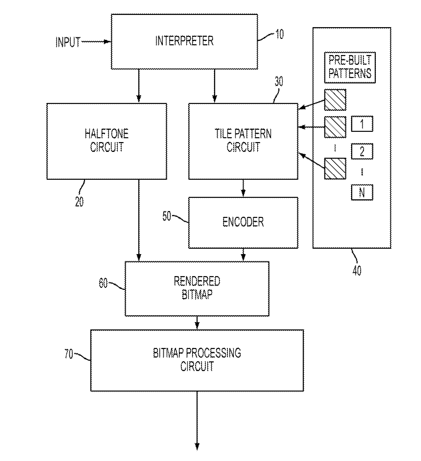
[0043]For a general understanding, reference is made to the drawings. In the drawings, like references have been used throughout to designate identical or equivalent elements. It is also noted that the drawings may not have been drawn to scale and that certain regions may have been purposely drawn disproportionately so that the features and concepts could be properly illustrated.

[0044]FIG. 1 shows, in schematic form, an image path of a reprographic system. The image path is a combination of hardware and software elements that generate and process the digital images.

[0045]As illustrated in FIG. 1, digital image data is input into an interpreter 10 that analyzes the image data to determine if the image data is picture image data or text / graphics image data. The interpreter 10 utilizes conventional image classification routines / circuitry or image segmentation routines / circuitry. An example of a conventional image classification routine / circuit is described in U.S. Pat. No. 5,765,029. T...


PUM


Abstract

An image processing system utilizes an image type classification circuit to identify inputted image data as picture image data or text/graphics image data. A halftone circuit, operatively connected to the image type classification circuit, converts the inputted image data, identified as picture image data, to halftone image data. Moreover, a tile pattern circuit, operatively connected to the image type classification circuit, to replace the inputted image data, identified as text/graphics image data, with tile patterns. Non-halftone cluster areas in the tile patterns are encoded with a predetermined pattern. A bitmap rendering circuit combines the halftone image data with the encoded tile patterns to render a bitmap, wherein the bitmap can be used by a print engine to reproduce the image.

Description

BACKGROUND AND SUMMARY[0001]Digital multifunction reprographic systems are well known and have replaced optical reprographic systems as a way to reproduce images. In these conventional digital multifunction reprographic systems, a scanner accepts a document to be copied and converts the document into electronic image(s). These images, usually in the form of pages, are then passed to a central control unit that may re-order or reorganize these pages and then, depending on the request of the user of the device, send the pages or images to a destination. Often this destination is an attached printing unit that makes one or more copies of the original document.[0002]However, these conventional devices perform many other functions besides simple copying. The central control unit is usually equipped with a combination of hardware and software elements that enable it to accept input from other sources. The other sources may include some sort of network interface and / or an interface to a te...

Claims


Application Information

Patent Timeline
IPC IPC(8): H04N1/405
CPCH04N1/40062H04N1/41H04N1/4092H04N1/405
Inventor STEVENS, MICHAEL DALE
Owner XEROX CORP
Why Eureka
Try Eureka