

Optical module
a technology of optical modules and optical components, applied in the field of optical modules, can solve the problems of insufficient focusing of the light-receiving lens by the imaging lens, high cost of conventional optical modules, and difficult fabrication
- Summary
- Abstract
- Description
- Claims
- Application Information
AI Technical Summary
Benefits of technology
Problems solved by technology
Method used
Image

Examples
first embodiment
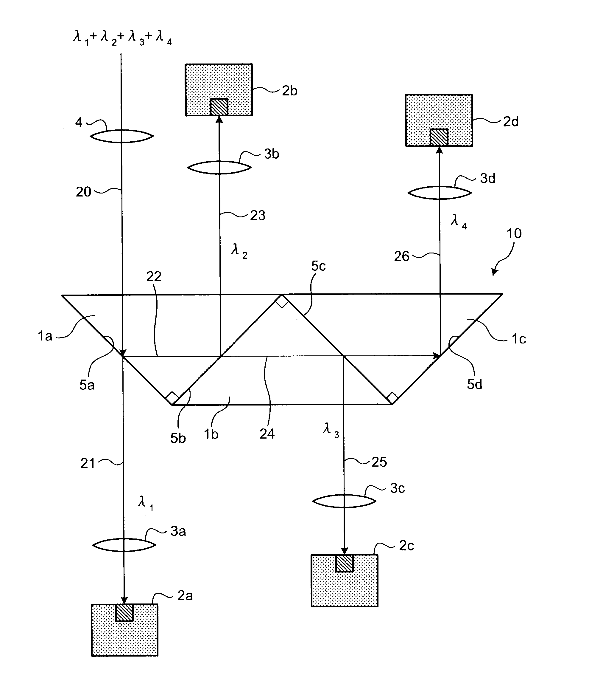
[0018]Exemplary embodiments of the present invention are described in detail below with reference to the accompanying drawings. FIG. 1 is a schematic diagram of a light-receiving device that includes an optical module according to the present invention. The light-receiving device shown in FIG. 1 is a 4-channel light-receiving module capable of receiving four channels of multiplexed optical signals having four different wavelengths.
[0019]The light-receiving device includes a wavelength separation filter 10, a collimating lens 4, a plurality of light-receiving elements 2a, 2b, 2c and 2d, and a plurality of imaging lenses 3a, 3b, 3c and 3d. When receiving optical signals, the collimating lens 4 converts the optical signals to collimated light and outputs the collimated light to the wavelength separation filter 10. The wavelength separation filter 10 separates the optical signals by their wavelengths. Each of the light-receiving elements 2a, 2b, 2c and 2d receives a corresponding one of...
second embodiment
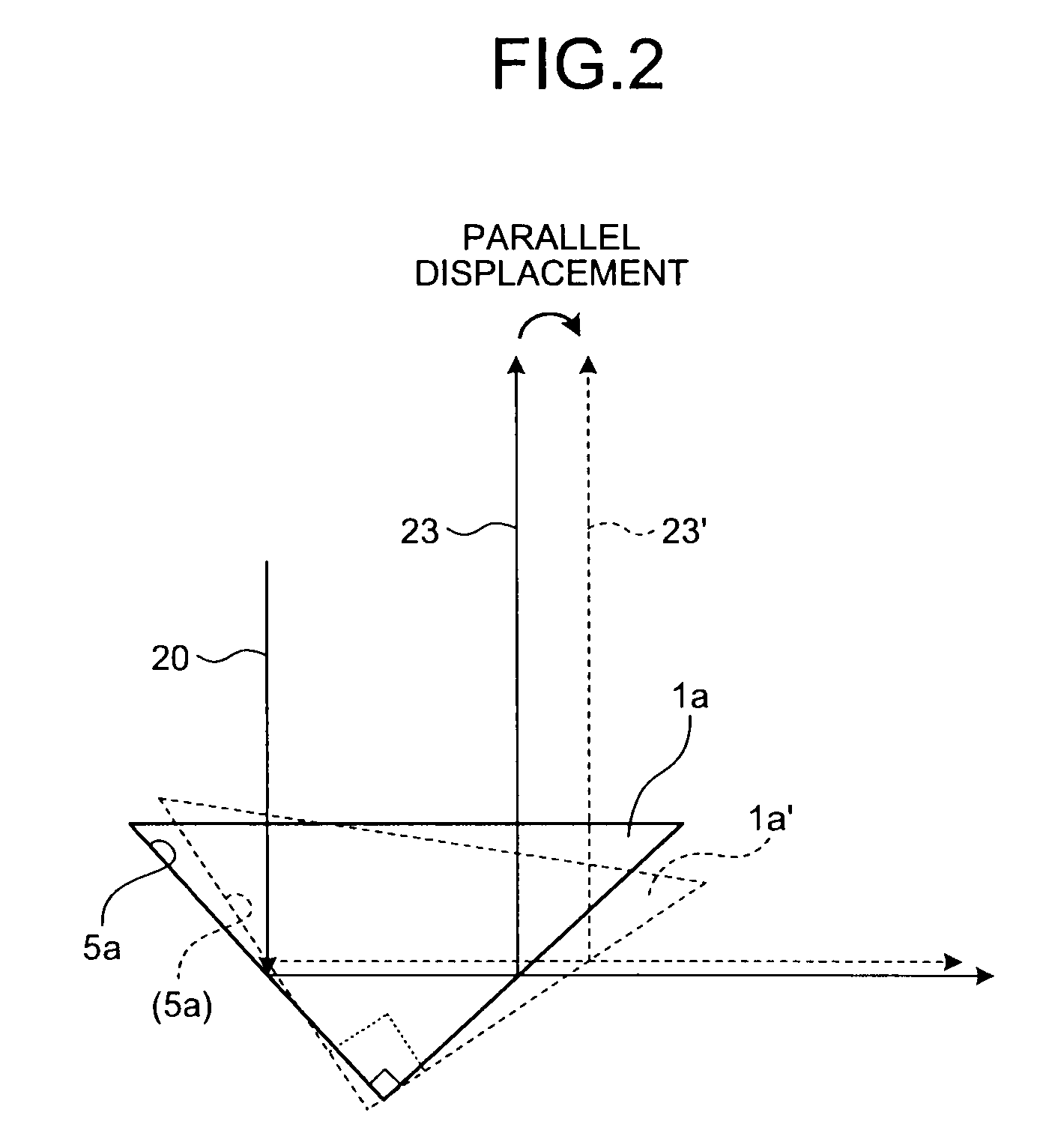
[0037]To solve the problem, in a light-receiving device shown in FIG. 4, a prism 30 is bonded to the surface 5a of the prism 1a from which the light 21 exits. More particularly, the prism 1a and the prism 30 are bonded together in such a manner that a surface 41 from which the light 21 exits becomes parallel to the base surface 40 from which the incident light 20 enters the prism 1a.
[0038]In other words, the prism 1a and the prism 30 are bonded together to form a single parallel plate. Accordingly, when the orientation of the wavelength separation filter 10 bonded with the prism 30 is displaced, even though the path of the output light 21 is displaced, the path of the output light 21 after the displacement is not inclined to but parallel to the path of the output light 21 before the displacement.
[0039]It means that the light-receiving device can be produced without taking into consideration a degree of tolerance for non-parallel displacement caused by the wavelength separation fil...
fourth embodiment
[0046]Because the lights output from fibers or laser lights are based on Gaussian beams, they cannot be converted to identical parallel lights, strictly speaking. Therefore, the light cannot always be the parallel light as the light travels further, so that the range in which the light can be practically parallel is limited. In the fourth embodiment, because the lengths of the paths along which the lights having the wavelengths λ1, λ2, λ3 and λ4 travel in the collimator optical system are set equal, the optical system for each wavelength can be made the same. This makes it possible to share certain components and reduce fluctuation in the optical performances.
[0047]A fifth embodiment of the present invention is described below. A light transmitting device according to the fifth embodiment has the configuration almost the same as the light-receiving device according to the first embodiment that has been described with reference to FIG. 1 except that the light-receiving elements 2a, 2...
PUM
 Abstract
Description
Claims
Application Information