Unloader system with cam operated raise system

a technology of unloading system and raise system, which is applied in the direction of loading/unloading vehicle arrangment, transportation items, refuse collection, etc., and can solve the problems of affecting productivity and efficiency, contact various obstacles, and lack of pressurized fluid capacity of the supplying machine or system for handling the additional fluid load of the conveyor

Inactive Publication Date: 2010-11-18
BLUE LEAF I P INC
View PDF23 Cites 17 Cited by
  • Summary
  • Abstract
  • Description
  • Claims
  • Application Information

AI Technical Summary

Benefits of technology

[0014]As an advantage of the invention, the conveyor can be configured in the stored position lowered and bent or folded downwardly alongside the support structure of the vehicle or container, so as to be more compact and less likely to contact and damage, or be damaged by, objects above the cart such as trees, utility wires, and the like. As another advantage, when in the operating position, the free end of the conveyor is raised by the raise system to a sufficient height for unloading into relatively tall receivers such as wagons, trailers and the like. As still another advantage, because of the use of the cam element for raising and lowering the conveyor, and also for unbending and bending the conveyor at the elbow, no pressurized fluid is required for these functions, and thus no load is placed on a fluid system of an accompanying vehicle such as a harvesting machine or the like for performing these functions. Also, as an advantage, as these functions occur as a result of only the movement of the conveyor between the stored and operating positions, no additional control circuit is required, and the unloading operation can be performed using only circuits for controlling an actuator or driver for pivoting the conveyor between the two positions, and for operating the conveyor.
, the conveyor can be configured in the stored position lowered and bent or folded downwardly alongside the support structure of the vehicle or container, so as to be more compact and less likely to contact and damage, or be damaged by, objects above the cart such as trees, utility wires, and the like. As another advantage, when in the operating position, the free end of the conveyor is raised by the raise system to a sufficient height for unloading into relatively tall receivers such as wagons, trailers and the like. As still another advantage, because of the use of the cam element for raising and lowering the conveyor, and also for unbending and bending the conveyor at the elbow, no pressurized fluid is required for these functions, and thus no load is placed on a fluid system of an accompanying vehicle such as a harvesting machine or the like for performing these functions. Also, as an advantage, as these functions occur as a result of only the movement of the conveyor between the stored and operating positions, no additional control circuit is required, and the unloading operation can be performed using only circuits for controlling an actuator or driver for pivoting the conveyor between the two positions, and for operating the conveyor.

Problems solved by technology

Due to limitations on the towing capacity of combines, the size or capacity of such carts or wagons is limited, and thus the cart or wagon must also be unloaded from time to time, often at different times or frequency than the unloading of the corn, which can have a negative effect on productivity and efficiency.
It is also commonly desired for an unloader conveyor to be carried on board a cart or wagon, but if the conveyor extends upwardly beyond the top of the cart, it can contact various obstacles, such as trees, low hanging wires, and the like.
As another potential problem wherein it is contemplated that an unload conveyor will be operated using pressurized fluid, there can be a lack of pressurized fluid capacity of the supplying machine or system for handling the additional fluid load of the conveyor, particularly when the conveyor includes high fluid demand devices such as fluid cylinders and the like.

Method used


Image

  • Unloader system with cam operated raise system
  • Unloader system with cam operated raise system
  • Unloader system with cam operated raise system

Examples


Embodiment Construction

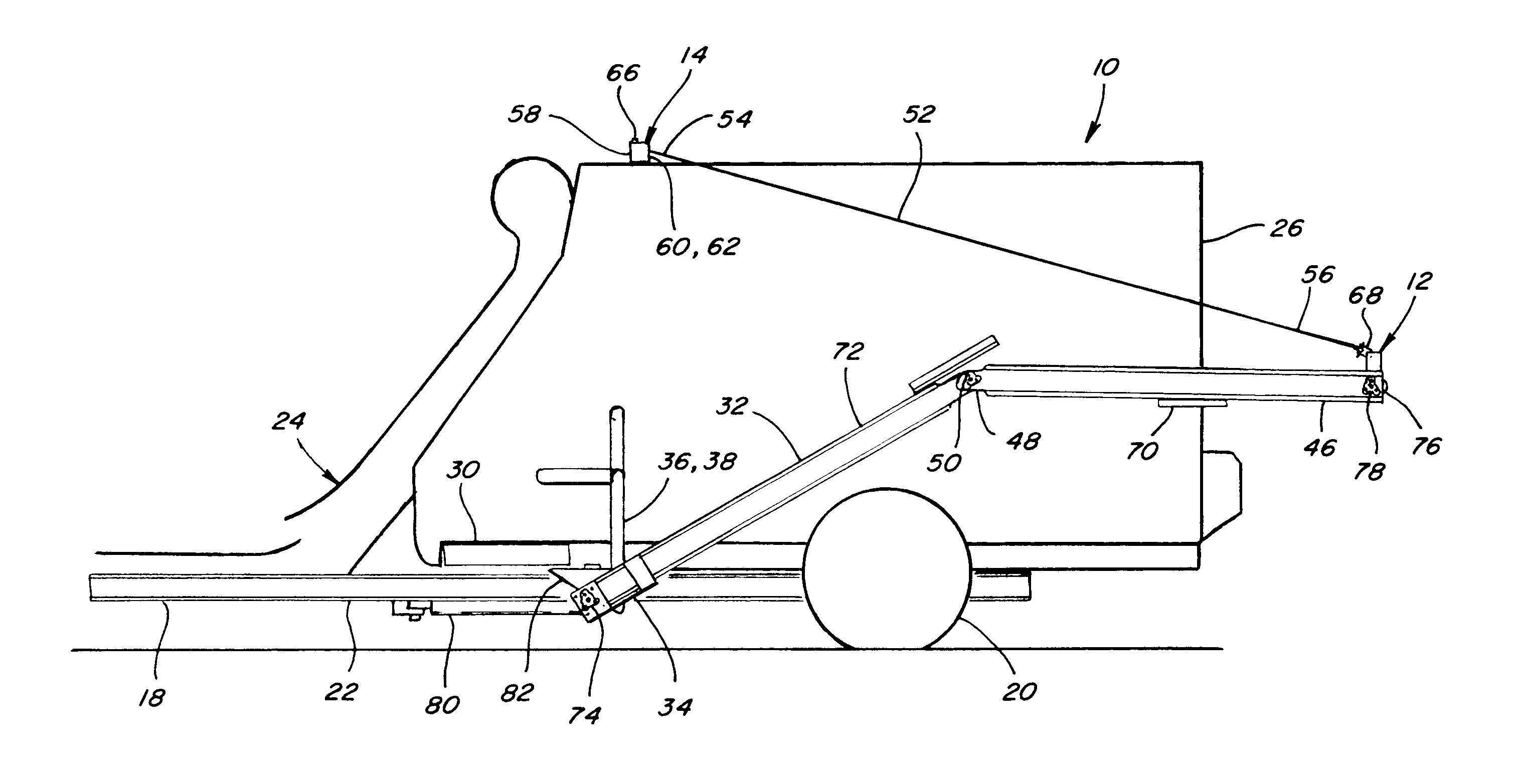
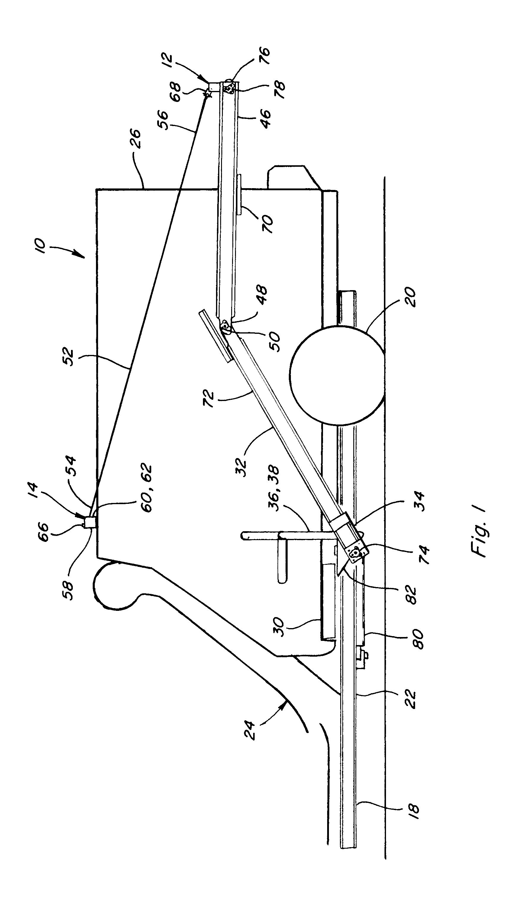
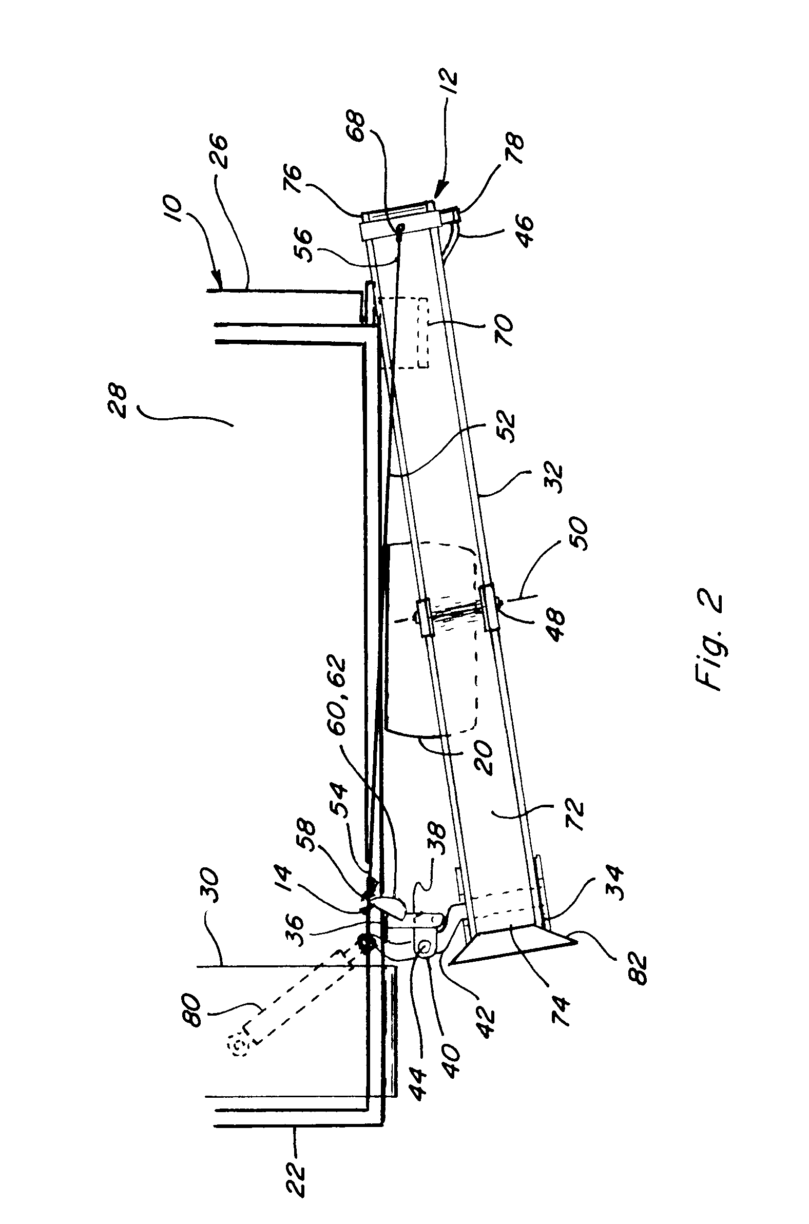
[0022]Referring now to the drawings, in FIGS. 1, 2, 3, 4, 5, and 6, a bulk materials cart 10 including an unloader system 12 having a cam operated raise system 14 constructed and operable according to the teachings of the present invention, is shown. Cart 10 as illustrated is configured for holding and unloading a wide variety of bulk materials, including, but not limited to, agricultural products such as corn cobs generated during corn harvesting operations in the well-known manner. Here, cart 10 is illustrated in FIG. 4 connected in towed relation to an agricultural harvesting machine 16 which is a combine operable in the well-known manner for harvesting ears of corn from corn plants, separating the kernels of corn from the cobs and other crop residue or stover, and discharging the cobs from the combine. Cart 10 can be connected to machine 10 in any suitable manner, such as, but not limited to, by a forwardly extending tongue 18 including structure such as a clevis, ball receiver,...


PUM


Abstract

The unloader system has a conveyor and a raise system having an elongate support element including a flexible first end portion and an opposite second end, the first end portion being connected to a support structure at a location higher than a first end of the conveyor, and the second end being connected to the conveyor at a location therealong adjacent to a free end thereof. A cam element is disposed on the support structure in a path of movement of the flexible first end portion of the support element such that as the conveyor is pivoted from the stored position toward the operating position the flexible first end portion will conformingly engage or bend about the cam element to raise the free end of the conveyor. The conveyor can include an elbow which is straightened by this action for raising the free end.

Description

[0001]This application claims the benefit of U.S. Provisional Application No. 61 / 216,521, filed May 18, 2009.TECHNICAL FIELD[0002]This invention relates generally to an unloader system for bulk materials such as agricultural crop material and the like, and more particularly, to an unloader system having a raise system for an unloader conveyor that automatically supports and raises a free end of the conveyor while optionally straightening it from a bent or folded condition, as the conveyor is pivoted from a stored position to an operating position.BACKGROUND OF THE INVENTION[0003]U.S. Provisional Application No. 61 / 216,521, filed May 18, 2009, is incorporated herein in its entirety by reference.[0004]A variety of bulk materials are conveyed by elongate conveyors carried on vehicles such as harvesters, carts, wagons, and the like, herein collectively referred to generally by the term cart. As a non-limiting example, are agricultural crop materials, such as silage, crop residue such as...

Claims


Application Information

Patent Timeline
Patent Type & Authority Applications(United States)
IPC IPC(8): B65G21/12B65G21/14B65G67/24B60P1/00B60P1/36B65G65/42
CPCA01D45/02A01D43/07
Inventor RICKETTS, JONATHAN E.WERNING, JOSHUA D.
Owner BLUE LEAF I P INC
Why Eureka
Try Eureka