Centrifugal impeller

Inactive Publication Date: 2010-11-18
ADD BLUE CORP
View PDF4 Cites 2 Cited by
  • Summary
  • Abstract
  • Description
  • Claims
  • Application Information

AI Technical Summary

Benefits of technology

[0012]The present invention is designed to overcome the above problems and it is an object of the present invention to provide a centrifugal impeller that allows a base plate to maintain an obtuse angle with respect to the rotational axis of the impeller so that fluid discharged at a high speed can smoothly pass through a passage between the base plate and a scroll casing and the volume for inlet flows can be enlarged.
[0017]According to the present invention, since the base plate of the centrifugal impeller is sloped within a range of 0° to 17° of the slope angle, high-speed fluid pushed in the centrifugal direction by rotation of the rotary shaft can smoothly flow through the enlarged channel that is widened as compared with the related art.
[0018]Further, since the base plate is sloped in the same direction as the scroll casing, even if the gap between the base plate and the scroll casing is decreased, as it is required to reduce the size of a product, and the axis of the impeller and the motion direction of the sucked fluid make an obtuse angle, not a right angle, the impact resistance of the fluid flowing at a high speed is reduced, thereby reducing noise and increasing the efficiency of the centrifugal impeller.

Problems solved by technology

However, there are problems in the related art described above.
In particular, as it is required to reduce the size of the product, the horizontal structure of the base plate 3 makes a gap between the base plate 3 and the scroll casing 7 narrower, which increases the impact resistance of the fluid flowing at a high speed, and as a result, generates a noise and decreases the efficiency of the centrifugal impeller 1.

Method used


Image

  • Centrifugal impeller
  • Centrifugal impeller
  • Centrifugal impeller

Examples


Embodiment Construction

[0024]Hereinafter, preferred embodiments of the invention are described in detail with reference to the accompanying drawings.

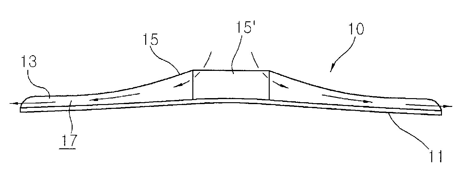
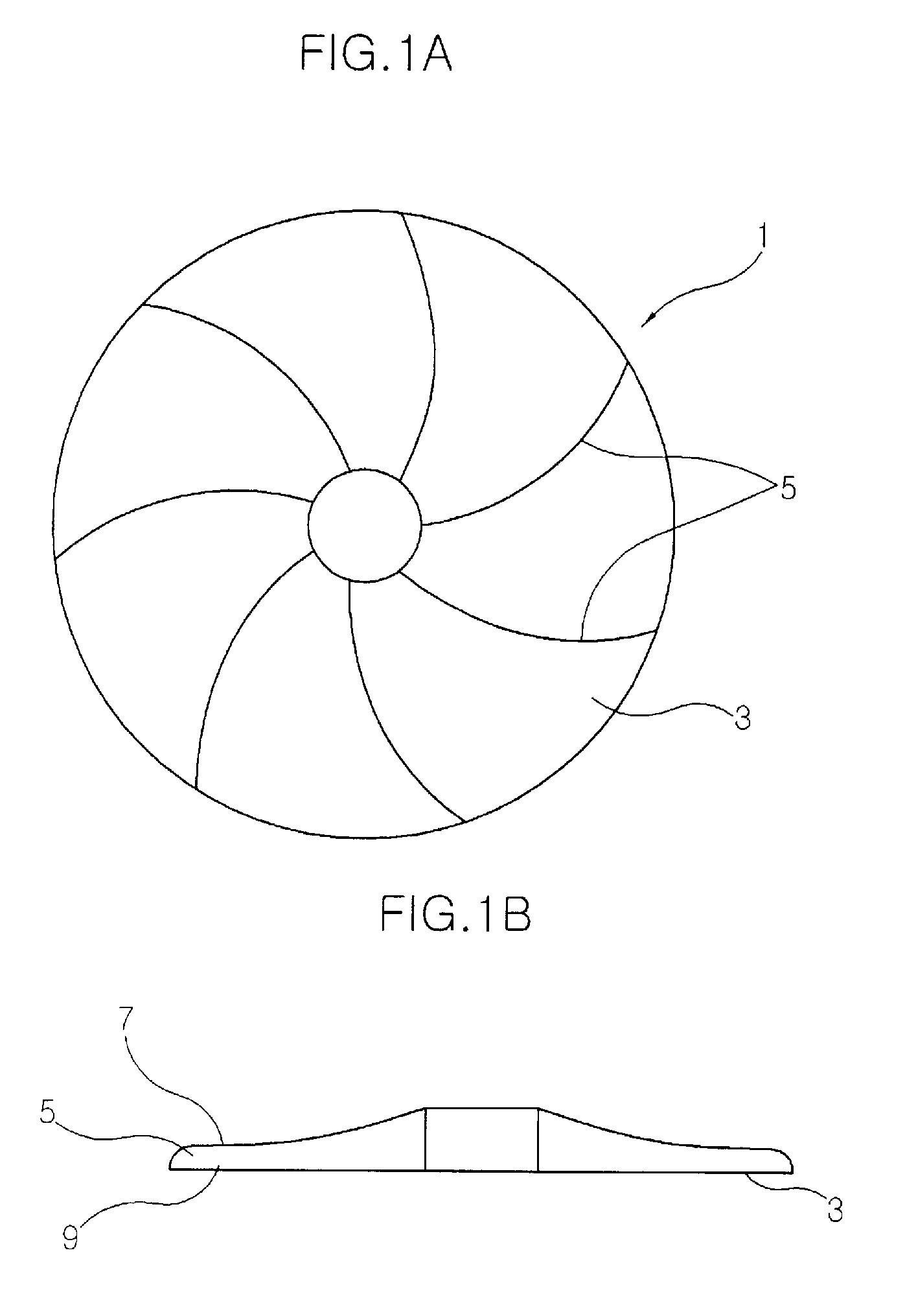
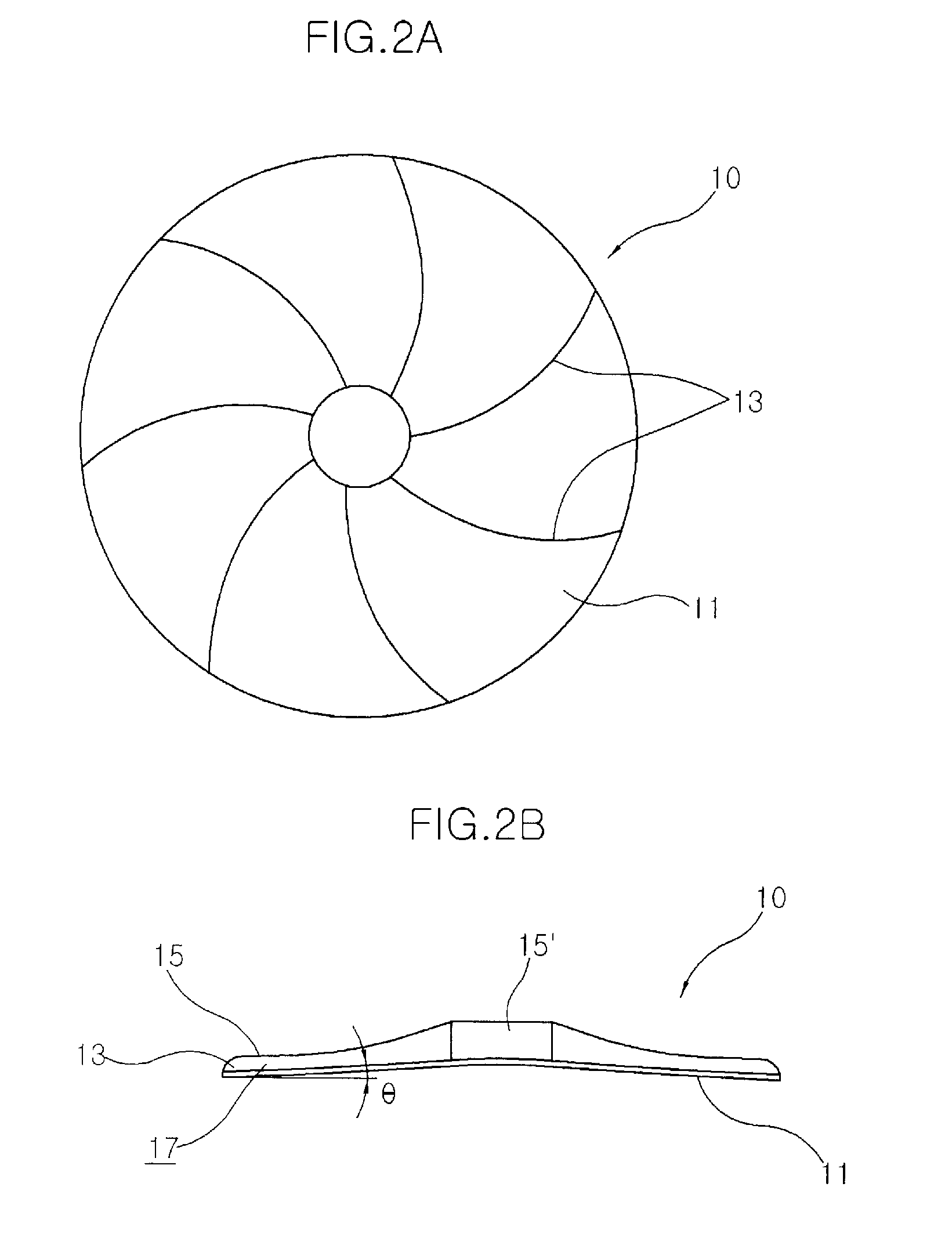
[0025]FIGS. 2A and 2B are a front view and a side view, respectively, showing a preferred embodiment of a centrifugal impeller according to the present invention, FIG. 3 is a view illustrating flow of fluid that flows through an enlarged channel according to the present invention, and FIG. 4 is a graph illustrating the relationship between the angle of a base plate and a coefficient of loss.

[0026]Referring to the figures a centrifugal impeller 10 includes a base plate 11 having a rotary shaft socket (not shown) at the center portion, blades 13 circumferentially arranged on the upper surface of the base plate 11, and a scroll casing 15 disposed at the fronts of the blades 13.

[0027]As shown in FIGS. 2A and 2B, the base plate 11 is a substantially circular plate, which forms the lower outer shape of the centrifugal impeller 10. The base plate 11 is sloped downwa...


PUM


Abstract

The present relates to a centrifugal impeller. According to the invention, the centrifugal impeller includes: a base plate 11 that has a rotating shaft bracket at the center portion where a rotary shaft is fitted, and of which the surface radially formed from the rotary shaft socket is sloped downward in a straight line or at a predetermined radius of curvature to maintain an obtuse angle with respect to the rotary shaft; a plurality of blades 13 that is circumferentially arranged on the upper surface of the base plate 11; and a scroll casing 15 that is disposed on the fronts of the blades 13, has a suction hole 15′ at the center portion to suck fluid, and forms an enlarged channel 17 through which the fluid flows, between the base plate 11 and the scroll casing 15 by being sloped downward from the suction hole 15′ toward the radial end. According to the present invention, the base plate 11 of the centrifugal impeller 10 is sloped within a range of 0° to 17° of the slope angle, such that high-speed jet fluid pushed in the centrifugal direction by rotation of the rotary shaft can smoothly flow through the enlarged channel 17 between the base plate 11 and the scroll casing 15.

Description

BACKGROUND OF THE INVENTION[0001]1. Field of the Invention[0002]The present invention relates to a centrifugal impeller, more particularly a centrifugal impeller that circumferentially discharges fluid smoothly, which is pushed by radial blades.[0003]2. Description of the Related Art[0004]A device that transports fluid using a suction force generated by high-speed rotation is called a centrifugal air blower. The centrifugal air blower is mainly used for air movements with high pressure such as vacuum cleaners that need strong output, and fluid is sucked into the centrifugal air blower by rotating centrifugal impellers at a high speed.[0005]FIG. 1A and FIG. 1B are a front view and a side view, respectively, which show the structure of a centrifugal impeller according to the related art.[0006]Referring to the figures, the centrifugal impeller 1 includes a base plate 3 having a rotary shaft socket at the center portion, radial blades 5 circumferentially arranged on the upper surface of...

Claims


Application Information

Patent Timeline
IPC IPC(8): F04D29/28F04D29/42
CPCF04D29/2255
Inventor KIM, KWANTAEJEON, JUNGIK
Owner ADD BLUE CORP
Why Eureka
Try Eureka