Pump arrangement comprising a safety valve

a safety valve and valve body technology, applied in the direction of pump control, pump components, positive displacement liquid engines, etc., can solve the problems of increased large dead volume between valve and pump, additional space and cost requirements, etc., to achieve size, weight and cost savings, the effect of minimizing the dead volume and space requirements

Active Publication Date: 2010-11-18
FRAUNHOFER GESELLSCHAFT ZUR FOERDERUNG DER ANGEWANDTEN FORSCHUNG EV
View PDF8 Cites 17 Cited by
  • Summary
  • Abstract
  • Description
  • Claims
  • Application Information

AI Technical Summary

Benefits of technology

[0016]Embodiments of the present invention provide a pump arrangement chip formed of several patterned layers arranged one above the other which form a pump and a safety valve integrated at the pump outlet. Thus, embodiments of the invention do not necessitate separate fluidic connections between pump and valve. Both dead volume and space requirements can be minimized in embodiments of

Problems solved by technology

Known micropumps are problematic in that free flow through the pumps may take place when an overpressure or positive pressure is applied to the inlet reservoir which is connected to the respective pump inlet, and there is no operating voltage applied to the pump.
When such a valve is to be combined with a pump in order to avoid free flow, increased space and cost requirements will result due to the separate component required.
Additionally, such an arrangement would result in a large dead volume between valve and pump, additionally requiring fluidic fittings or connections therebetween.
Nevertheless, separate components are needed, resulting in additional space and cost requirements.
Additionally, such double normally closed microvalves have only been available in silicon, which is expensive.
Additionally, when being connected to a micropump, there i

Method used


Image

  • Pump arrangement comprising a safety valve
  • Pump arrangement comprising a safety valve
  • Pump arrangement comprising a safety valve

Examples


Embodiment Construction

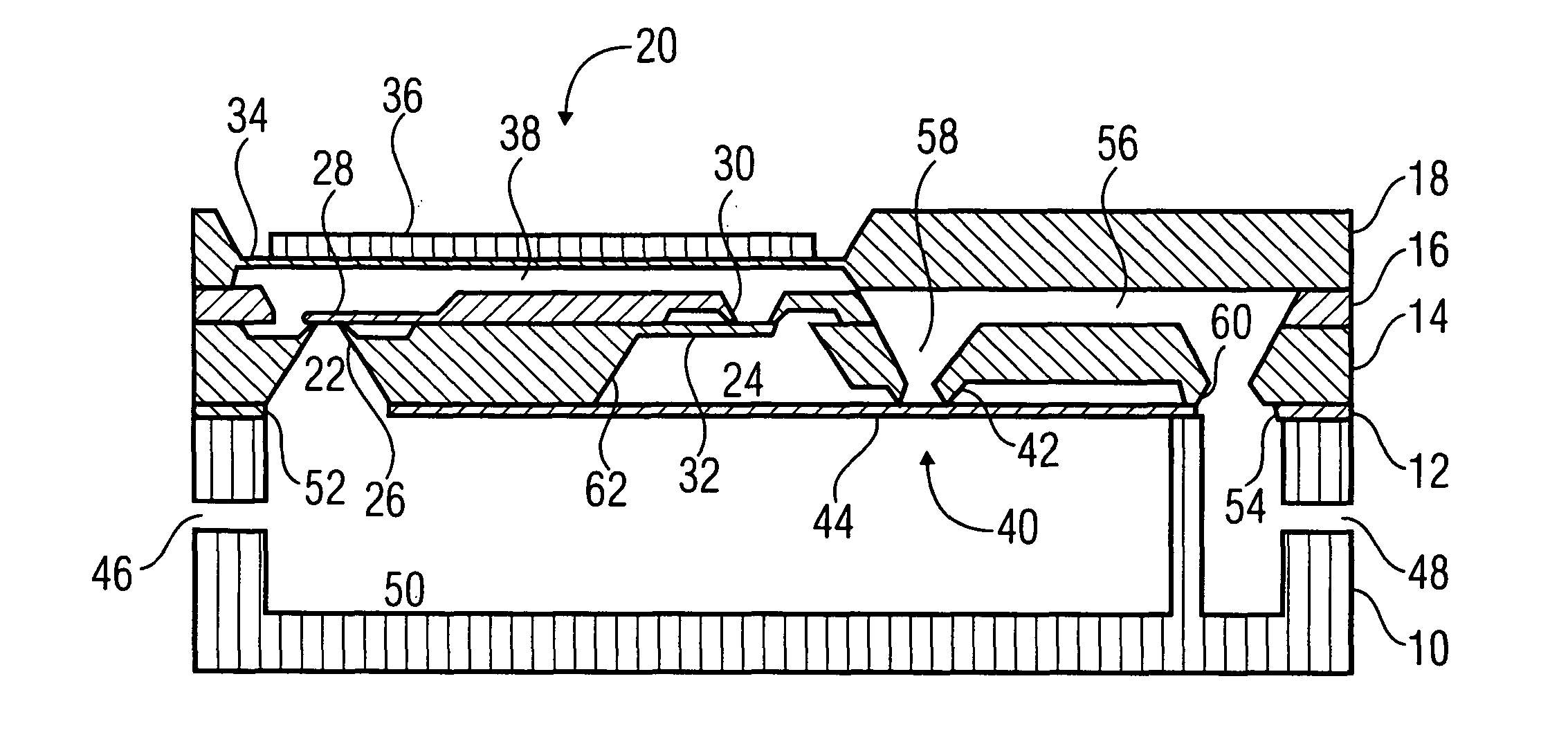
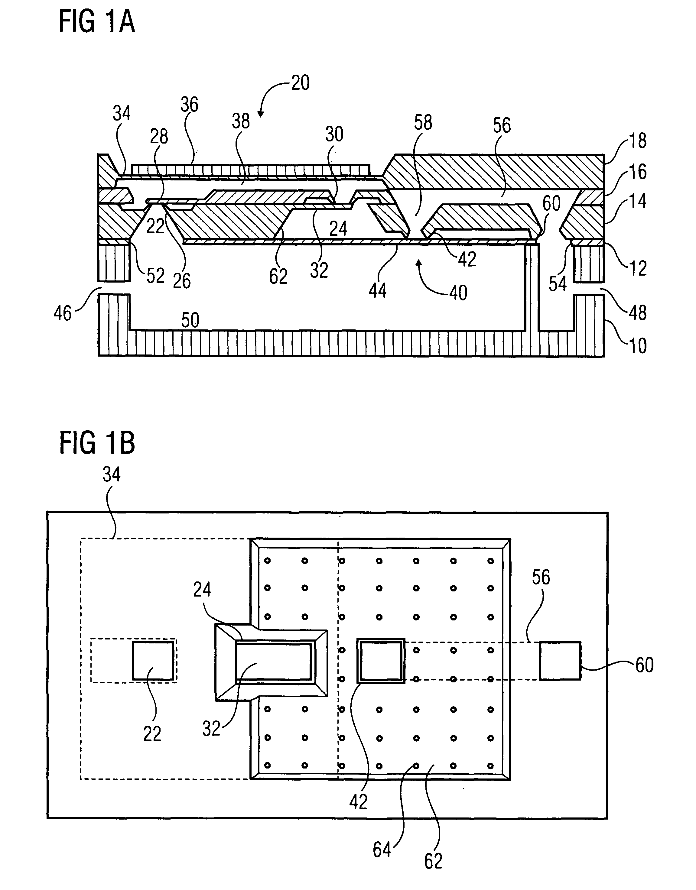
[0025]Referring to FIGS. 1a and 1b, an embodiment of an inventive pump arrangement wherein a pump is implemented by a micro-diaphragm pump comprising passive check valves will be described below.

[0026]In accordance with the embodiment shown in FIGS. 1a and 1b, the pump arrangement includes five patterned layers which are arranged one above the other and attached to one another. These layers will subsequently be referred to as first layer 10, second layer 12, third layer 14, fourth layer 16 and fifth layer 18.

[0027]The pump arrangement shown in FIG. 1a comprises a diaphragm pump 20 comprising a pump inlet 22 and a pump outlet 24. The pump inlet 22 and the pump outlet 24 are patterned in the bottom surface of the third layer 14. The diaphragm pump 20 includes a passive check valve comprising a valve seat 26 and a valve flap 28, at the pump inlet 22. The valve seat 26 is patterned in the top surface of the third layer 14 and the valve flap 28 is patterned in the fourth layer 16. Additi...


PUM


Abstract

A pump arrangement includes a pump having a pump inlet and a pump outlet, and a safety valve arranged between the pump outlet and an outlet of the pump arrangement and having a valve seat and a valve lid. The valve seat, the pump outlet and the pump inlet are patterned in a first surface of a first integrated part of the pump arrangement, whereas the valve lid is formed in a second integrated part of the pump arrangement. An inlet of the pump arrangement and a fluid region fluidically connected thereto are formed in a third part of the pump arrangement. The second integrated part is arranged between the first integrated part and the third part of the pump arrangement such that a pressure in the fluid region has a closing effect on the safety valve, the pump inlet and the inlet of the pump arrangement being connected fluidically.

Description

BACKGROUND OF THE INVENTION[0001]Embodiments of the invention relate to a pump arrangement and, in particular, to a pump arrangement comprising a safety valve at a pump outlet of a pump.[0002]Diaphragm pumps comprising passive check valves at the pump inlet and the pump outlet are exemplarily known from DE-A-19719862. Peristaltic pumps comprising no active valve are exemplarily known from DE-A-10238600. In particular, the above documents disclose micropumps, which are taken as such pumps the pump volume of which when being actuated once are in a range of microliters or below.[0003]Known micropumps are problematic in that free flow through the pumps may take place when an overpressure or positive pressure is applied to the inlet reservoir which is connected to the respective pump inlet, and there is no operating voltage applied to the pump.[0004]Normally closed self-blocking valves are known from DE-A1-10048376 and WO-A1-2004 / 081390. A normally closed valve is to be taken as a valve ...

Claims


Application Information

Patent Timeline
IPC IPC(8): F04B43/04F04B53/10
CPCF04B43/043F04B49/10F04B43/12F04B43/14
Inventor RICHTER, MARTINKRUCKOW, JUERGEN
Owner FRAUNHOFER GESELLSCHAFT ZUR FOERDERUNG DER ANGEWANDTEN FORSCHUNG EV
Why Eureka
Try Eureka