Electrical network command and control system and method of operation

Inactive Publication Date: 2010-11-18
CONSOL EDISON OF NEW YORK
View PDF12 Cites 69 Cited by
  • Summary
  • Abstract
  • Description
  • Claims
  • Application Information

AI Technical Summary

Problems solved by technology

The system presents these potential issues and possible corrective actions to the network operator.

Method used


Image

  • Electrical network command and control system and method of operation
  • Electrical network command and control system and method of operation
  • Electrical network command and control system and method of operation

Examples


Embodiment Construction

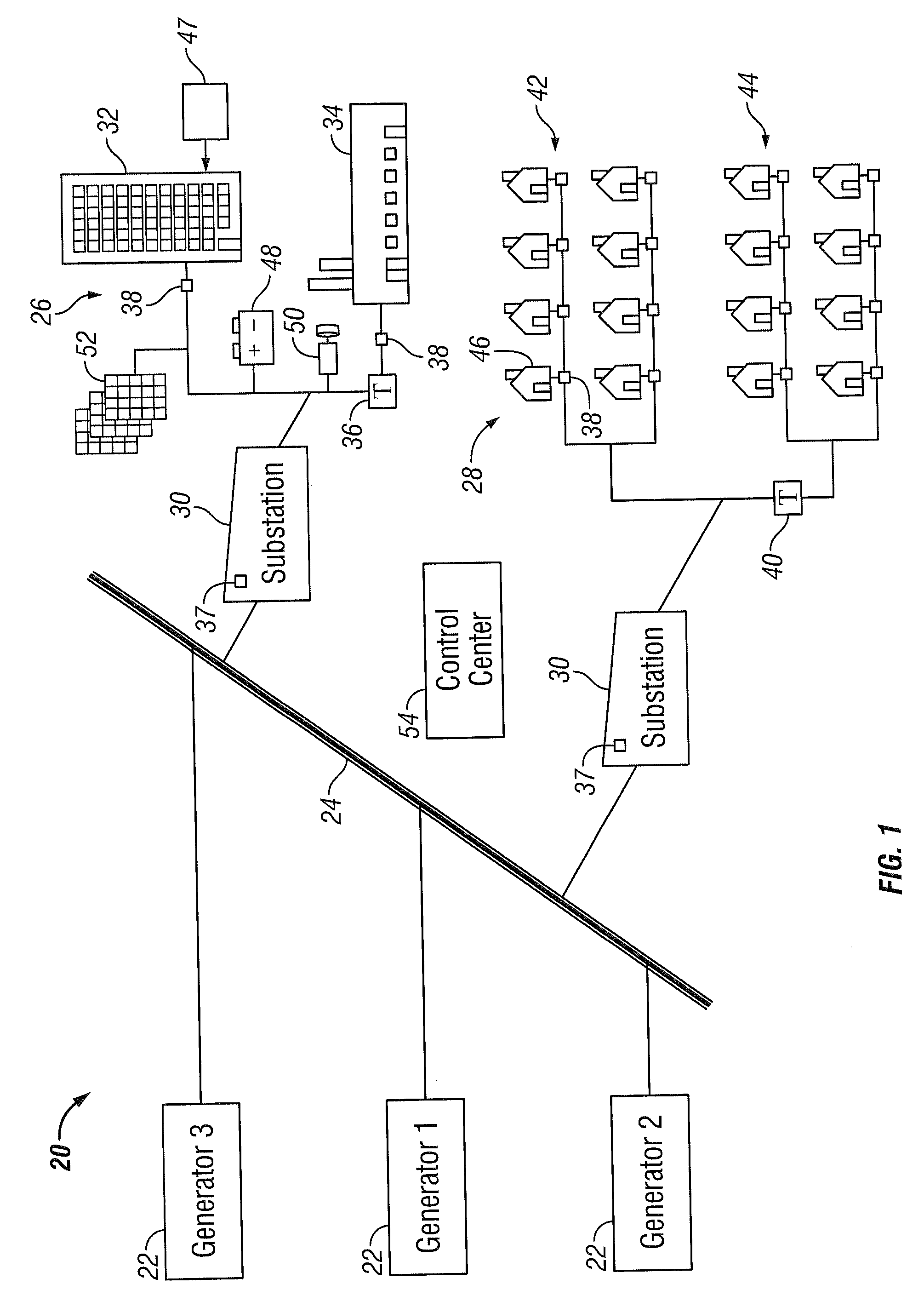
[0013]FIG. 1 illustrates an exemplary embodiment of a utility electrical distribution network 20. The utility network 20 includes one or more power plants 22 connected in parallel to a main transmission network 24. The power plants 22 may include, but are not limited to: coal, nuclear, natural gas, or incineration fueled power plants. Additionally, the power plants 22 may include one or more renewable hydroelectric, solar, or wind turbine power plants. It should be appreciated that additional components such as transformers, switchgear, fuses and the like (not shown) may be incorporated into the utility network 22 as needed to ensure the safe and efficient operation of the system. As discussed in more detail below, the utility network 20 may be interconnected with one or more other utility networks to allow the transfer of electrical power into or out of the electrical network 20.

[0014]The main transmission network 24 typically consists of high voltage or medium voltage power lines,...


PUM


Abstract

A system is provided that allows the aggregation of a plurality of inputs from an electrical grid and the display of the plurality of inputs on a single integrated display for a network operator. The system accepts signals from electrical loads and generation devices and analyzes the inputs to determine potential issues or trends, including fault predictions and recommends contingency plans. The system presents these potential issues and possible corrective actions to the network operator. The network operator may initiate actions, such as dispatching loads or activating generation capacity for example, in response.

Description

BACKGROUND OF THE INVENTION[0001]The present invention relates generally to a system for managing an electrical network and more particularly to a system that aggregates, analyzes and assists the network operator in balancing electrical power generation and demand on the electrical networks.[0002]The delivery of electrical power from a power generation plant to an end customer takes many routes. The electrical power is transmitted from the power generation plant to a high voltage transmission system that includes conductors and equipment for the transfer of the electrical power over long distances. Coupled to the transmission system at different locations are substations that transfer and transform the high voltage electrical power into a medium voltage distribution system. This medium voltage distribution system in turn delivers the electrical power to a low voltage distribution near the point of use (e.g. a residential neighborhood). This process involves many miles of conductors ...

Claims


Application Information

Patent Timeline
Patent Type & Authority Applications(United States)
IPC IPC(8): G06F1/28G06G7/63G01R21/00G06F19/00
CPCG05B15/02H02J13/001H04Q9/00Y04S10/30H04Q2209/60Y02E60/74H04Q2209/10H04Q2209/75Y04S10/40H02J13/00001H02J13/00002H02J13/00034Y02E60/00
Inventor BOSE, SANJAYKRESSNER, A. ARTHUR
Owner CONSOL EDISON OF NEW YORK
Why Eureka
Try Eureka