Data migration management apparatus and information processing system

Inactive Publication Date: 2010-11-18
HITACHI LTD
View PDF7 Cites 61 Cited by
  • Summary
  • Abstract
  • Description
  • Claims
  • Application Information

AI Technical Summary

Benefits of technology

[0014]Accordingly, an object of the present invention is to provide a data migration management apparatus and an information processing system that make it possible to set and execute a data migration relatively easily. Another object of the present invention is to provide a data migration management apparatus and an information processing syst

Problems solved by technology

However, in a method that makes use of backup data, the host computer is prohibited from accessing the migration-targeted data until data reallocation has ended.
Therefore, the processing of work on the host computer must stop until data reallocation is over, lowering usability.
This increases the I/O (Input/Output) load of the migration-targeted data.
If host computer access frequency is high in this case, the processing load of the storage controller increases, lengthening the time required for a data copy to be completed.
Not only that, but when processing is carried out giving priority to host computer access, there is also the possibility of a data copy process ending in error a

Method used


Image

  • Data migration management apparatus and information processing system
  • Data migration management apparatus and information processing system
  • Data migration management apparatus and information processing system

Examples


Example

First Embodiment

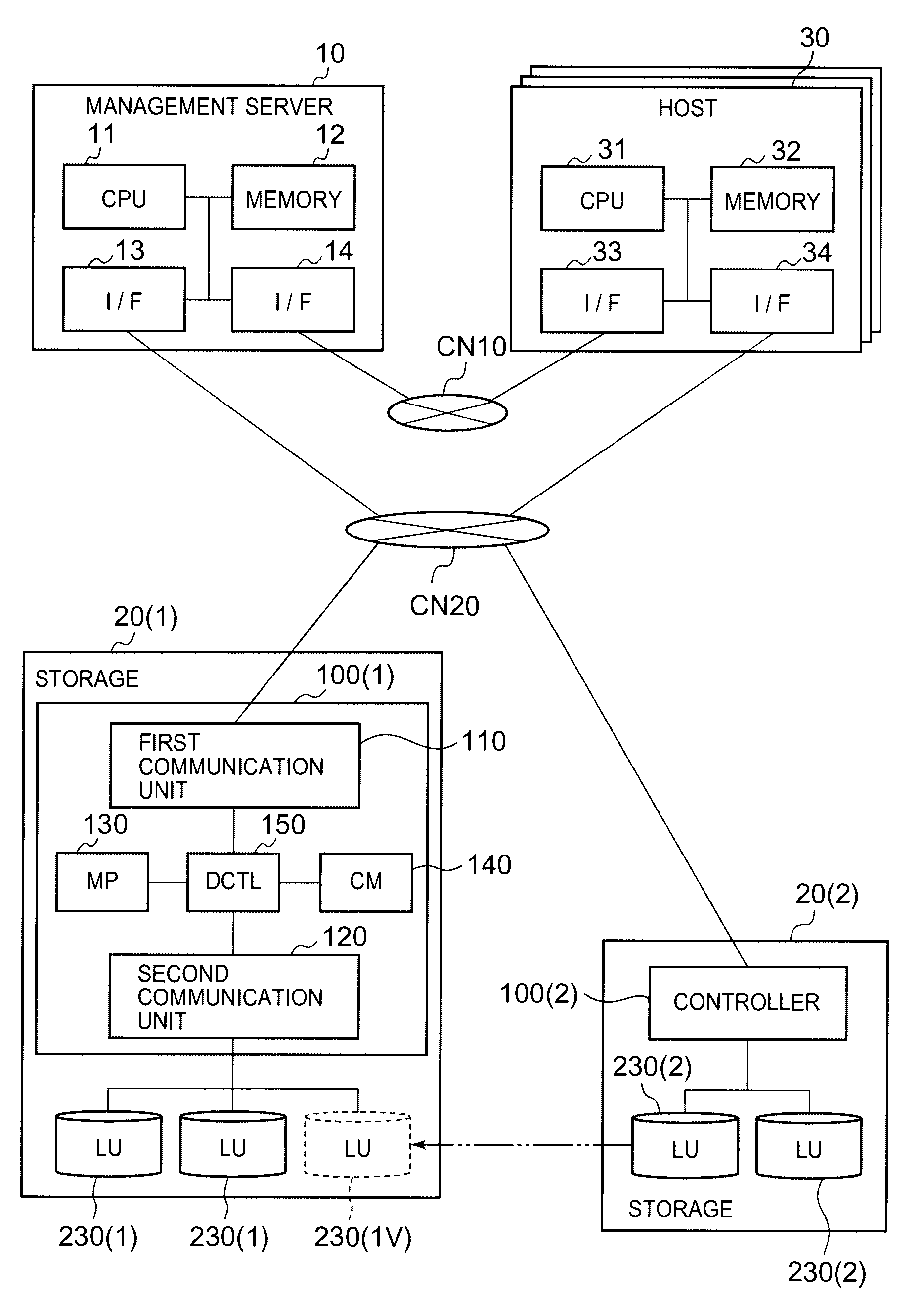
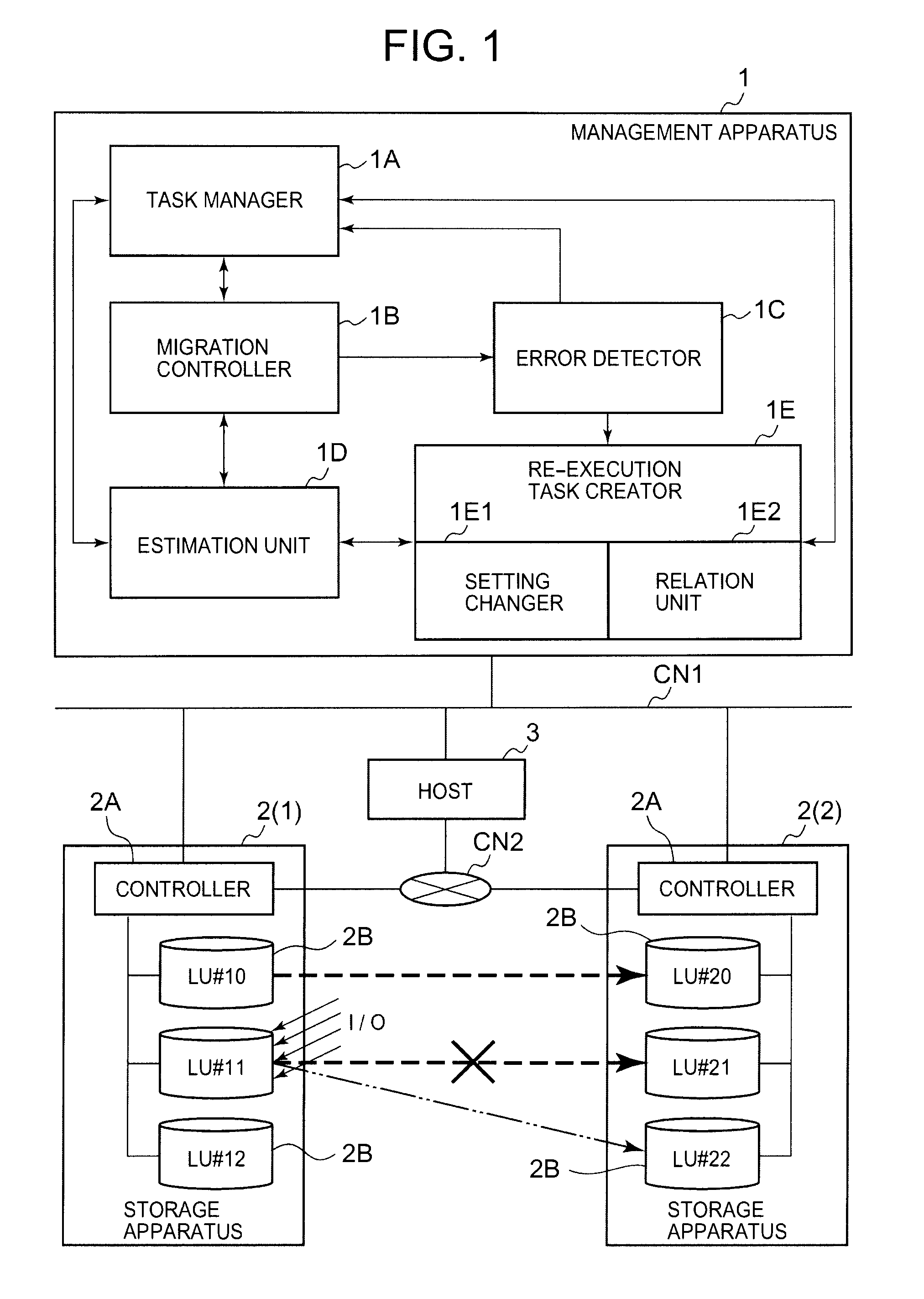
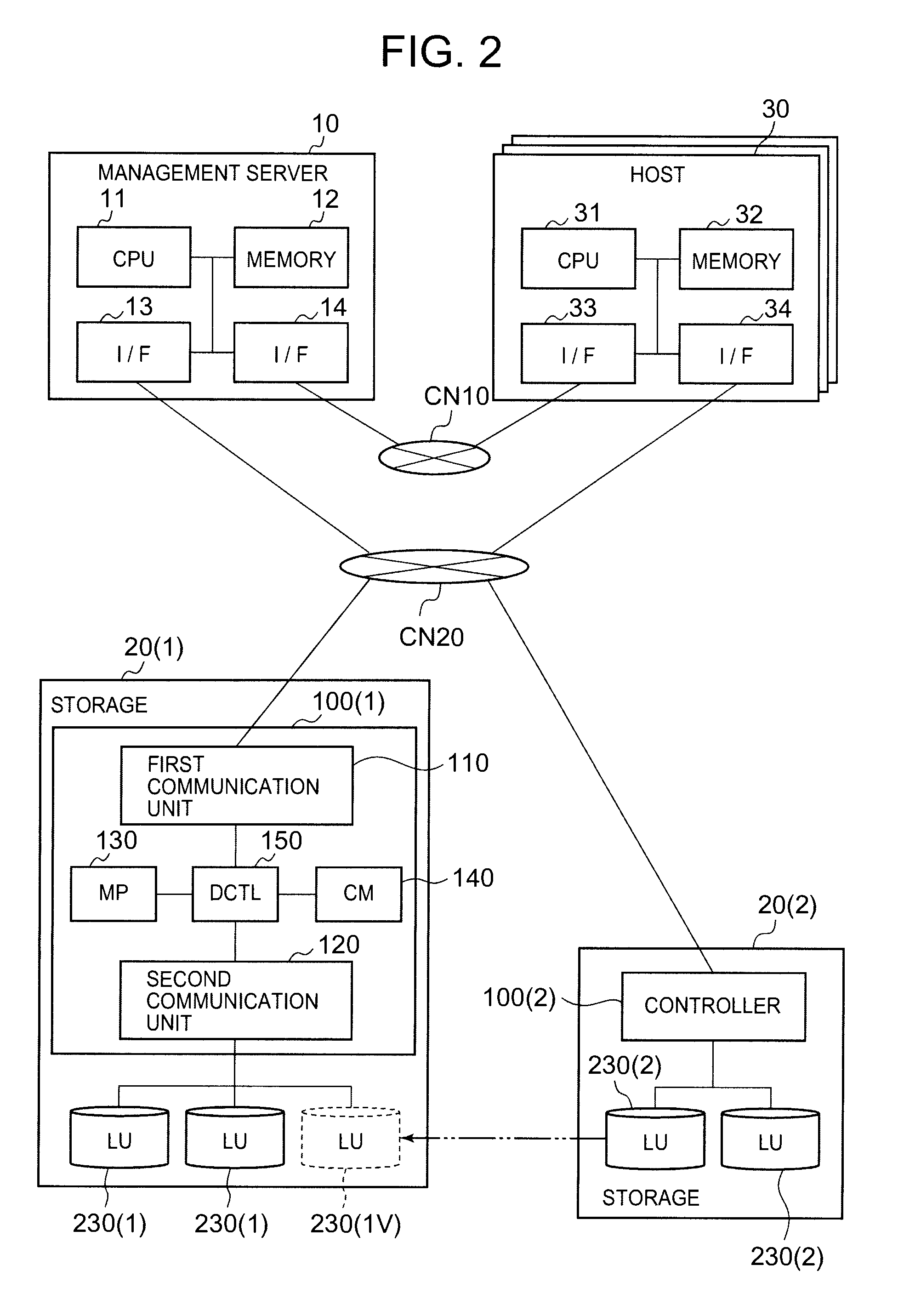
[0083]The first embodiment will be explained based on FIGS. 2 through 19. FIG. 2 is a schematic diagram showing the configuration of an overall system. The relationship to the configuration shown in FIG. 1 will be described first. The management server 10 corresponds to the management apparatus 1, the storage apparatuses 20(1), 20(2) correspond to the storage apparatuses 2(1), 2(2), the host 30 corresponds to the host 3, the controllers 100 correspond to the controllers 2A, and the logical volumes 230 corresponds to the logical volumes 2B.

[0084]In this embodiment, the management server 10, for example, is connected to respective hosts 30 via a communication network CN10 such as a LAN. In addition, the management server 10 is connected to the respective storage apparatuses 20 via a communication network CN20 such as a SAN. Furthermore, the configurations of the communication networks are not limited to those shown in FIG. 2.

[0085]The management server 10 is for managi...

Example

Second Embodiment

[0213]A second embodiment will be explained based on FIG. 20. The following embodiments, to include this embodiment, are equivalent to variations of the first embodiment. Therefore, in the embodiments that follow, the explanations will focus on the differences with the first embodiment. In the second embodiment, when a candidate volume is retrieved, a logical volume, whose important attributes match those of the initially selected migration-destination volume, is retrieved.

[0214]FIG. 20 is a flowchart showing a volume pair re-selection process that is implemented by the management server 10 according to this embodiment. This process comprises S90 and S92 through S94 in common with the process shown in FIG. 19; only S91A differs.

[0215]In the case of a migration-destination volume error (S90: YES), the management server 10 references a table T60 for managing attributes in order of priority, and retrieves a candidate volume whose highest priority attribute matches the ...

Example

Third Embodiment

[0219]A third embodiment will be explained based on FIGS. 21 and 22. In this embodiment, in a case where a retryable error has occurred in a data migration, the volume pair configuration is changed based on an estimation result for the data migration completion time. FIG. 21 is a flowchart showing the re-execution task creation process implemented by the management server 10 of this embodiment.

[0220]The management server 10 determines whether or not there is a task that ended in an error (S100). When an error-terminated task exists (S100: YES), the management server 10 determines whether or not this error-terminated task is a re-execution task (S101).

[0221]In a case where either no error-terminated task exists (S100: NO) or the error-terminated task is a re-execution task (S101: YES), the management server 10 proceeds to the error process shown in FIG. 22 (S111). In the error process, for example, a prepared error message is notified to the user.

[0222]Return to FIG. ...


PUM


Abstract

The present invention provides a data migration management apparatus that can easily create a re-execution task for re-executing an error-terminated data migration task, and also can increase the possibility of the re-execution task being successful. In a case where a data migration from a migration-source volume to a migration-destination volume fails, the management apparatus uses the information of the failed task to create a re-execution task. The management apparatus changes the configuration of a volume pair as necessary. The management apparatus manages the failed task in association with the re-execution task.

Description

CROSS-REFERENCE TO RELATED APPLICATIONS[0001]This application relates to and claims priority from Japanese Patent Application No. 2009-116486 filed on May 13, 2009, the entire disclosure of which is incorporated herein by reference.BACKGROUND OF THE INVENTION[0002]1. Field of the Invention[0003]The present invention relates to a data migration management apparatus and an information processing system.[0004]2. Description of the Related Art[0005]The amount of data being handled by companies is increasing every year. For this reason, companies are using a plurality of different storage controllers to construct relatively large-scale information processing systems that manage large volumes of data. Since the frequency with which data is utilized will decrease in accordance with the passage of time, the location where data is stored is reallocated in accordance with the data utilization frequency.[0006]Accordingly, the effective use of the storage resources inside a data processing syst...

Claims


Application Information

Patent Timeline
IPC IPC(8): G06F11/14G06F9/46G06F12/16G06F11/00
CPCG06F3/0617G06F3/0647G06F3/067G06F11/0715G06F11/0775G06F11/1464G06F11/1497G06F11/0727
Inventor SAKAGUCHI, AKIHIKOYAMAKAWA, HIROSHI
Owner HITACHI LTD
Why Eureka
Try Eureka