Drive mechanism and drive device

Inactive Publication Date: 2010-11-25
KONICA MINOLTA OPTO
View PDF35 Cites 21 Cited by
  • Summary
  • Abstract
  • Description
  • Claims
  • Application Information

AI Technical Summary

Benefits of technology

[0045]According to the present invention, in a drive mechanism and a drive device to which an SMA actuator is applied, a driven body is connected to a fixed portion via a viscoelastic member. As a result, the driven body is prevented from vibrating and deterioration of the SMA is prevented. Furthermore, a predetermined portion of a displacement member that receives a driving force from the SMA actuator to displace the driven member is connected to the fixed portion via a viscoelastic member. This helps alleviate the stress of the SMA actuator generated

Problems solved by technology

However, the servo control, when performed at a high speed, causes the drive mechanism including the SMA to vibrate, taking a long time to make a lens stop at a target position in a stable state, and this is inconvenient.
Furthermore, the whole drive mechanism is caused to oscillate, which not only makes it impossible to control the position of a lens but also results in a problem that the drive mechanism itself is damaged.
Moreov

Method used


Image

  • Drive mechanism and drive device
  • Drive mechanism and drive device
  • Drive mechanism and drive device

Examples


example 1

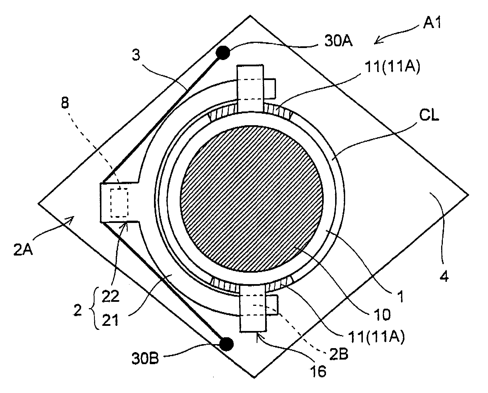
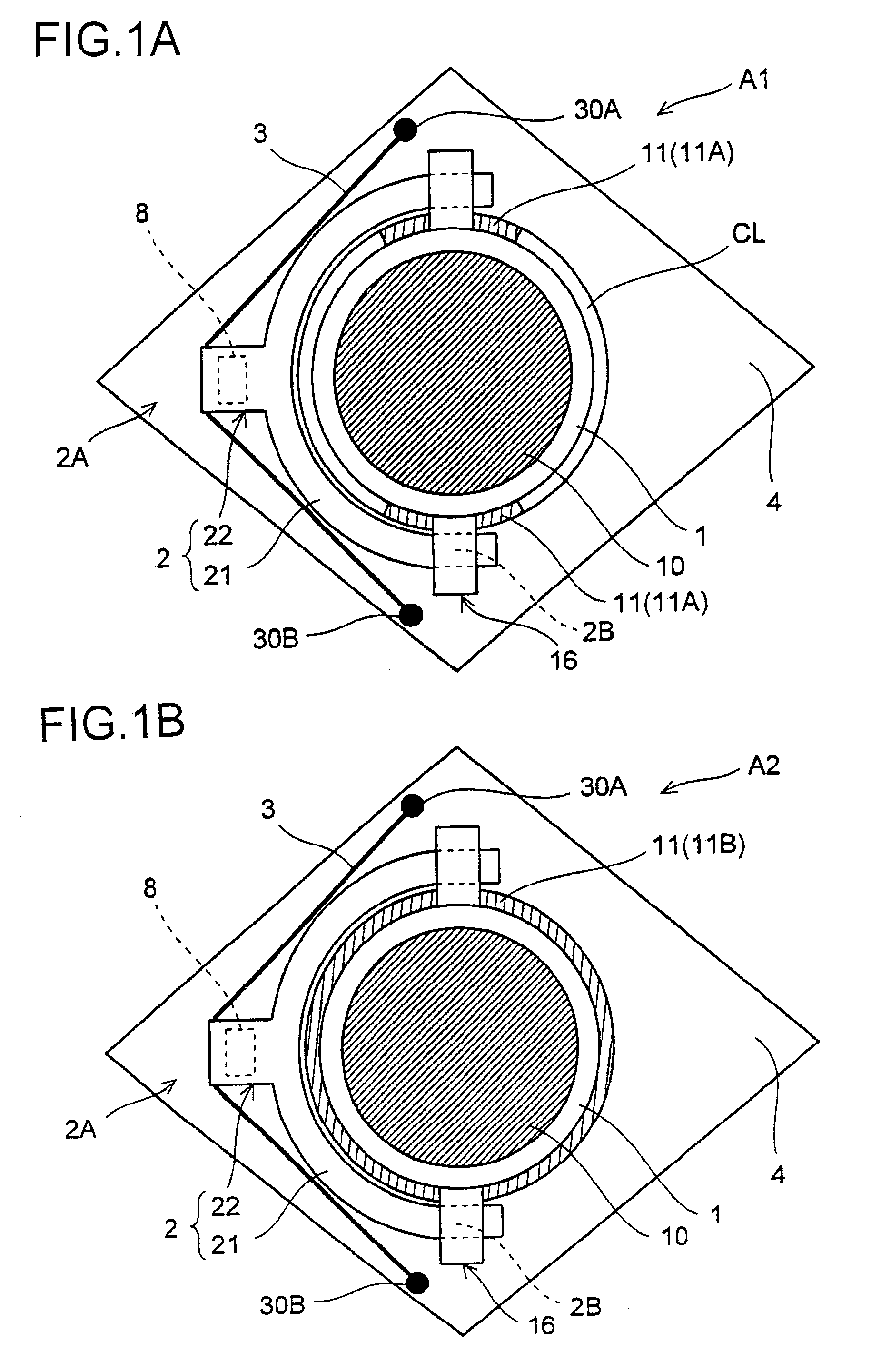
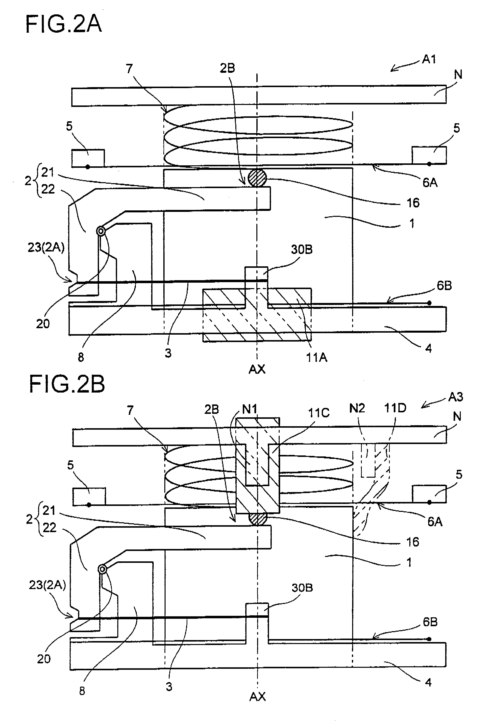
[0099]Next, a description will be given of a drive device A1 of a first embodiment which is provided with a drive mechanism of the present invention and provided with a viscoelastic member, with reference to FIGS. 1(a) and 2(a). First, descriptions will be given of a fitting position of the viscoelastic member that the drive device A1 of the first embodiment has and its effect. The drive device A1 is structured such that a viscoelastic member 11 (11A) is interposed in a clearance CL between a driven body 1 and a through hole portion of a base member 4, and the driven body 1 and the base member 4 are connected to each other via the viscoelastic member 11 (11A).

[0100]For the purpose of reciprocating the driven body 1 in an axis direction, the drive device A1 is provided with: a shape memory alloy wire 3 fitted by being placed in an L-shape or a U-shape surrounding outside of the driven body 1 with the suspension portion 23 as a winding portion; and a lever member 2 that amplifies a di...

example 2

[0126]Even when the shape memory alloy wire 3 is not energized, if it is exposed to a high-temperature environment, it shows a response similar to that it shows when it is energized. That is, under a high-temperature environment, the shape memory alloy wire 3 starts transformation to generate a stress, which is a feature of the shape memory alloy. This state will be described with reference to FIG. 7.

[0127]As shown in FIG. 7(a), under a high-temperature environment, the shape memory alloy wire 3 starts to transform and a stress F4 is generated. As a result, the lever member 2 receives a driving force that tends to drive the lever member 2 to rotate, and via the pivotally-supporting portion 20, the driving force acts on the support leg 8 as a stress F5. Also, a stress F6 acts on the electrode 30B.

[0128]Here, if base portions of the base member 4, the support leg 8, and the electrode 30B are made of resin such as plastics, and left in such a stress-applied state for a long time, the r...


PUM


Abstract

A drive mechanism and a drive device each comprise a driven body (1), a displacement member (2), and an SMA actuator (3) for giving a displacement force. The driven body (1) is coupled to a fixed section through a viscoelastic member (11 (11A, 11B, 11C, 11D)). A displacement output section is engaged with the driven body, and thereby a predetermined portion of the displacement member (2) for displacing the driven body in a first-axis direction is connected to the fixed section through the viscoelastic member (11 (11E, 11F, 11G, 11H)). A shape-memory alloy (SMA) actuator is used. The position of the driven body is stably and quickly controlled. Even if a shock force is exerted or even if the drive mechanism and the drive device are left in a high-temperature environment for a long time, the SMA, the drive mechanism, and the drive device do not deteriorate, the sizes and weights thereof can be reduced, and they can be easily assembled.

Description

TECHNICAL FIELD[0001]The present invention relates to a drive mechanism and a drive device which drive a compact machine element by use of a shape memory alloy actuator. In particular, the present invention relates to a drive mechanism and a drive device which are suitable for moving a lens unit constituting a shooting optical system in an optical axis direction.BACKGROUND ART[0002]In recent years, image quality of image sensors has been drastically improved as seen in, for example, the increase in number of pixels in image sensors mounted in camera phones and the like. Along with such improvement, there has been a demand for sophisticated functions such as a focusing function and a zoom function to be provided in addition to the basic function of shooting.[0003]A lens drive device moving a lens in an optical axis direction is necessary for provision of such sophisticated functions, and researches have recently been conducted on various methods of application of a lens drive device ...

Claims


Application Information

Patent Timeline
IPC IPC(8): F03G7/06
CPCF03G7/065G02B27/646G02B7/08
Inventor NODA, ATSUHIROWADA, SHIGERU
Owner KONICA MINOLTA OPTO
Why Eureka
Try Eureka